Carrier SYSTEM PILOT 33PILOT-01 User Manual
Page 5
5
CONFIG AND SETPOINT TABLES — If the CONFIG or
SETPOINTS table option is selected from the Program screen,
and if there is more than one entry in the corresponding table
list, then the System Pilot displays a Table List screen. If there
is only a single table, the System Pilot displays the contents of
the table.
Only two types of configuration tables will be available in
Security Level 2, Holiday Configuration tables and Occupancy
tables (if attached to a device with an occupancy schedule).
NOTE: The CONFIG function is not available if the System
Pilot is set to Security Levels 3 or 4. The SETPOINTS func-
tion is not available if the system is set to Security level 3.
The top line of the Table List screen shows the table type
that was selected. The bottom line shows text and error mes-
sages, as applicable. The center portion of the screen shows the
table list. This consists of the table names from the specified
list, arranged in alphabetical order.
Use the SCROLL UP/DOWN buttons or the NAVIGATE
knob to scroll through the list. Press the SELECT button to
display the highlighted line.
If a table type with multiple table entries was selected, the
System Pilot will display a Multiple Table List screen with all
of the table names associated with that table type.
If it is a table type with a single table entry, the System Pilot
will display a Standard Table screen.
Multiple Table List Screen — If multiple tables of a selected
type are available, or if SCHEDULE is selected from the Pro-
gram screen and there are multiple schedules, the System Pilot
will display a Multiple Table List screen with all of the table
names associated with that table type.
The top line shows the name of the table that was selected.
The bottom line shows text and error messages, as applicable.
The center portion of the screen lists the associated tables in
alphabetical order. If the list has more than 7 tables, then the
first 7 tables will be displayed.
Use the SCROLL UP/DOWN buttons or the NAVIGATE
knob to scroll through the list. If there are more than 7 tables,
pressing PAGE UP/DOWN will display the previous or next 7
names from the list. Press the SELECT button to read the
highlighted table from the attached device and display an
appropriate screen. A Time Schedule screen is displayed if the
table is a time schedule, or a Standard Table screen is displayed
for any other table. Pressing the EXIT button causes the
System Pilot to return to the Table List screen.
Standard Table Screen — If a table type with a single table en-
try is selected from a Table List screen, or a table (other than a
schedule) is selected from a Multiple Table List screen, the
System Pilot displays a Standard Table screen.
The top line shows the 8-character table name. The center
portion of the screen shows the table data.
Configuration and set point data is read from the attached
device once, when the table is first selected and displayed.
There will be one point/decision per line. If there are more than
seven decisions/points, the first seven will be displayed. The
bottom line displays text and error messages, as applicable.
Use the SCROLL UP/DOWN buttons or the NAVIGATE
knob to scroll through the data. If there are more than 7 deci-
sions/points, pressing PAGE UP/DOWN will display the
previous or next 7 decisions/points. As the user scrolls through
the table, the System Pilot will highlight the current decision/
point and if there is an associated point name, the 24-character
descriptor will be displayed on the bottom line. If there is no
associated point name, the System Pilot will display the
24-character descriptor in the center portion of the screen.
If the SELECT button is pressed and the current point is ed-
itable, the System Pilot allows the user to modify the point.
If the EXIT button is pressed, the System Pilot exits to the
next higher screen.
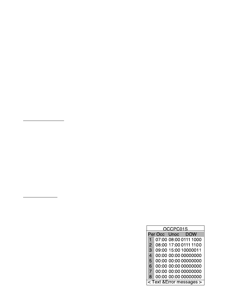
SCHEDULE — Selecting the SCHEDULE option from the
Program screen and then selecting a Time Schedule table
displays the Time Schedule screen as shown in Fig. 11. This
example shows all 8 of the time schedule periods, even though
only the first 6 (plus the header line) will actually be shown on
the System Pilot when this screen is entered.
NOTE: This function is not available if the System Pilot is set
to Security Levels 3 or 4.
The top line shows the 8-character schedule name. The
bottom line displays text and error messages, if applicable. The
center portion of the screen shows the schedule data which are
the occupied and unoccupied times for each period and the
days to which the period applies. The time is displayed with a
24-hour clock with colon (00:00 to 24:00). The day flags are
displayed as 8 bits (0 or 1), for Monday through Sunday plus
holiday. The times and day flags are modifiable. The period
numbers and the header line are fixed. Each of the day flags is
treated as a separate field, therefore, there are 12 modifiable
fields per line.
Use the SCROLL UP/DOWN buttons or the NAVIGATE
knob to scroll through the table one line at a time. If the
SELECT button is pressed, the System Pilot allows the user to
modify the data on the current line (starting with Occupied
hour). Use the NAVIGATE knob to move within the line. As
each field is highlighted, the truncated 24-character descriptor
is displayed on the message line. Use the INC/DEC buttons or
the MODIFY rotary knob to adjust the highlighted value. If the
EXIT button is pressed, the System Pilot will return to the
Program screen or the Multiple Table List screen.
DETACH — Select this option from the Program screen to
disconnect from the device to which the System Pilot is
currently attached. The System Pilot will attach to itself and
display the System Pilot default screen.
Modifying Set Points —
The VVT® zone controller
default screen displays two set points. The Remote Attach
Default screen will display up to two set points. The user can
modify the displayed set points by turning the MODIFY rotary
knob or pressing the INC/DEC buttons. The displayed set
points will blink.
NOTE: This function is not available if the System Pilot is set
to security level 4.
The System Pilot will modify a set point subject to the
limits read from the controller. If there are two set points, the
System Pilot will modify them simultaneously and will
preserve the difference between them subject to the limits read
from the controller.
The System Pilot has configurable high and low limits for
set points, as defined in the System Pilot Configuration Table
and the System Pilot remote attach configuration table. On a
Remote Attach Default screen, the limits will be applicable to
606
→
→
Fig. 11 — Time Schedule Screen