Carrier SYSTEM PILOT 33PILOT-01 User Manual
Page 2
2
User Interface —
The System Pilot contains six buttons
and two rotary knobs with buttons, which allow the user to
navigate through the menus, select the desired options, and
modify data. See Fig. 5.
SCROLL UP/SCROLL DOWN — If displaying a table or a
list of items, these buttons move the cursor to the next line or
previous line in the table or list.
If the System Pilot is displaying a controller Default screen
and the SCROLL UP and SCROLL DOWN buttons are
pressed together for 3 seconds, the System Pilot changes to
Program mode.
Pressing the SCROLL UP button along with the INC/DEC
button increases or decreases the contrast on the System Pilot
LCD display screen.
PAGE UP/PAGE DOWN — In screens that have more than 7
data lines (Ex: a Table List screen with more than 7 tables, or a
table with more than 7 decisions), these buttons replace the
items currently on the screen with the previous or next 7 items
from the table or list.
If there is additional data at the end or beginning of a table
or list that is not on the screen, the cursor will not advance
(move down) past the next-to-last line or up past the second
line on the screen.
Linkage Coordinator Zone Controller Bus Scan — Pressing
PAGE UP/PAGE DOWN together for 3 seconds from the
Default screen of a Linkage Coordinator Zone Controller
Default screen will display the Bus Scan screen. Bus Scan
allows the user to scan through the linkage coordinator’s zones
and display what is found at each address. Refer to Bus
Scan section on page 7 for additional information on Linkage
Coordinator Zone Controller Bus Scan.
INC/DEC — The INC and DEC buttons modify the value of
the highlighted field within its defined limits.
From the Zone Controller Default screen, the INC/DEC
buttons allow the user to modify the set points. Pressing the
INC/DEC buttons continuously updates the highlighted field
and the rate of change accelerates over time.
NAVIGATE — This rotary knob functions like the SCROLL
UP/DOWN buttons, with the same sort of wrap-around. How-
ever, it also incorporates a left-right movement. The cursor
moves one selectable field with each increment of the rotary
knob. Turning the knob clockwise moves the cursor to the right
and down. With each increment, the cursor advances to the
next field to the right on the current line. If the cursor is on the
last field in the line, the cursor advances to the first (left-most)
field in the next line. Turning the knob counterclockwise
moves the cursor to the left and up in the same manner.
The NAVIGATE rotary knob also functions as the EXIT
button when pressed.
EXIT — The EXIT button returns the display to the next high-
er screen in the hierarchy. If the EXIT button is pressed and the
data on the screen cannot be or has not been modified, the
System Pilot moves to the next higher screen immediately (no
additional prompts).
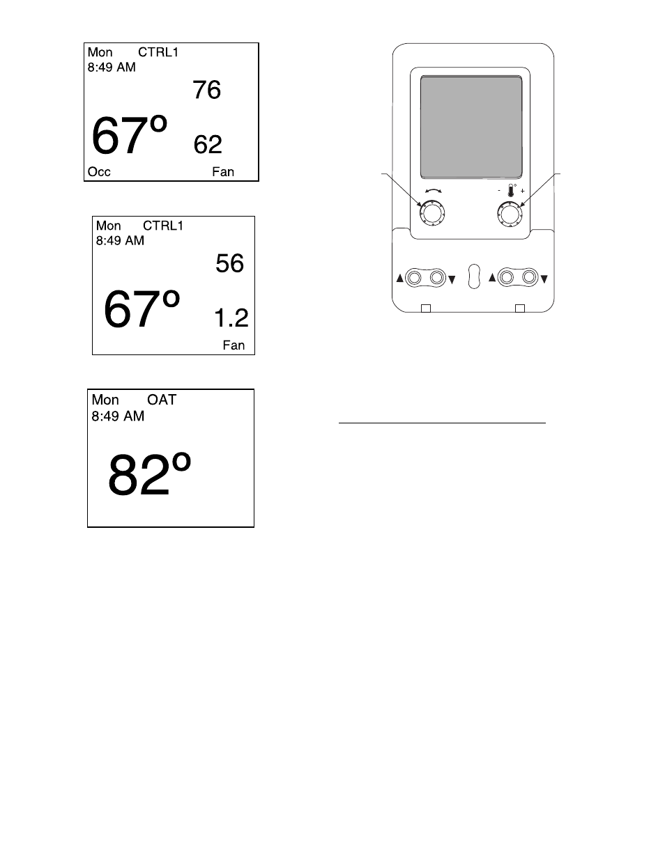
Fig. 3 — Bypass Controller Default Screen
Fig. 2 — Zone Controller Default Screen
Fig. 4 — OAT Display Screen
SCROLL
+
-
NAVIGATE/
EXIT
MODIFY/
SELECT
PAGE
Fig. 5 — System Pilot User Interface
606
→
→