SINGER 143G2 User Manual
Page 10
Attention! The text in this document has been recognized automatically. To view the original document, you can use the "Original mode".
To Set the Needle Bar
See that the needle Is up In the bar as far as It will
ko
.
There are two lines 3/32 Inch apart across the needle bar
about two Inches above the lower end. When the needle bar Is at
Its lowest position, the UPPER MARK should be Just visible at the
lower end of the needle bar frame.
16
£2H<)3
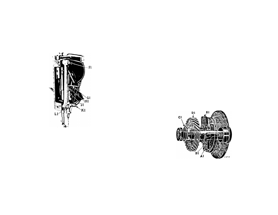
Fig. 19. Face Plate Removed
In case the needle bar Is not correctly set, loosen the
needle bar connecting stud set screw (HI,Fig.19) and move the
needle bar to the correct position, then tighten the set screw.
TO SET A NEEDLE BAR WHICH HAS NO MARK: Set the needle bar so
that when It rises 3/32 Inch from Its lowest position, the eye of
the needle will be about 1/16 Inch below the point of the hook as
the hook point enters the thread loop.
To Set and Time the Needle Bar Frame
First turn
the needle vibrator spindle head (A,Fig.2) all the
way to the right so that the needle will not vibrate when the ma
chine Is running. A straight needle should now come In the cen
tre
of
the
needle
hole
In
the
throat
plate.
If
It
does
not,
loosen
the
set
screw
which
holds
the
eccentric
stud
(Kl,Flg.l9)
ind turn the stud (KL) until It does, then tighten the set screw.
Now
turn
the
needle
vibrator
regulating
spindle
head
to
the
left
for
the
widest
throw.
Turn
the
machine
pulley
toward
you
until
the
needle
Is
at
Its
lowest
position.
As
the
needle
bar
starts
to
rise,
the
needle
bar
frame
should
start
to
move
side-
wise.
If
It
does
not,
advance
or
retard
the
vibrator
gear
pin
ion (M,Flg. 5).
To Remove the Needle Vibrator Gear Shaft
Remove
the
needle
vibrator
regulating
spindle
head
(A,Fig,2)
and the eccentric bracket cover (C,Flg.2); remove the locking and
adjusting
screws
(A1
and
Bl,Flg.20),
also
the
screw
and
spring
(El). Loosen the two set screws In the gear (Dl) and remove the
needle
vibrator
gear
shaft
collar
(L,Flg.3)
at
the
back
of
the
arm, then draw the shaft out.
When replacing these parts be careful that the large washer
(Cl,Fig.20) Is In place between the gear and arm, that the posi
tion
screws
are
set
firmly
against
the
flat
spots
on
the
shaft
and that the set screws are at the right of the position screws
when the shaft has been returned to Its place.
TO SET THE NEEDLE VIBRATOR REGULATINO SPINDLE HEAD SO
THAT A WIDER THROW THAN THE OJE DESIRED CANNOT BE MADE:
17
Fig. 20. Transparent View Showing the Needle Vibrator
Regulating Spindle Head In Front of Machine
Turn
the
spindle
head
(A,Fig.2)
to
make
the
widest
bight
possible; remove locking screw (Al,Flg.20) and turn In screw (Bl)
until
the
stitch
Is
of
the
width
desired;
then
turn
screw
(Al)
down tightly on screw (Bl) as a check. The width of stitch may
then
be
decreased
by
turning
the
regulating
spindle
head,
but
operators
cannot
make
stitches
wider
than
the
adjusting
screw
(Bl) Is set to produce.