Depth of cut adjustments, Depth stop rings, Operation – Sears 315.17473 User Manual
Page 6
Attention! The text in this document has been recognized automatically. To view the original document, you can use the "Original mode".
OPERATION
WARNING; BEFORE CONNECTING YOUR ROUTER TO POWER SUPPLY SOURCE, ALWAYS CHECK
TO BE SURE SWITCH IS NOT IN "LOCK-ON” POSITION. FAILURE TO DO SO COULD RESULT IN
ACCIDENTAL STARTING OF YOUR ROUTER RESULTING IN POSblSLE SERIOUS INJURY.
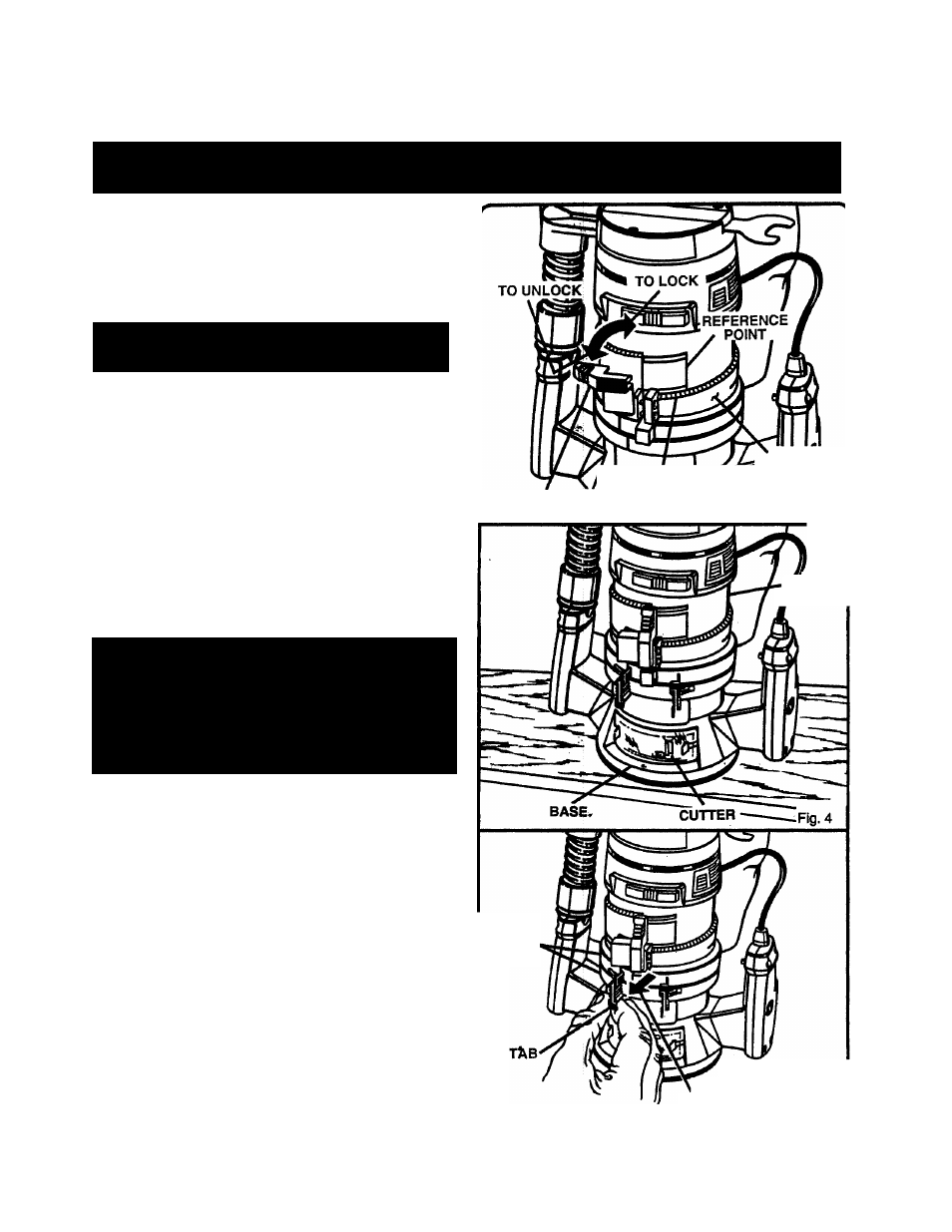
DEPTH OF CUT ADJUSTMENTS
See Figures 3 and 4.
We recommend that cuts be made at a depth not exceeding
1 /8 in. and that severai passes be made to reach depths of cut
greater than 1/8 in.
1. UNPLUG YOUR ROUTER.
WARNING:
FAILURE TO UNPLUG YOUR
ROUTER COULD RESULT IN ACCIDENTAL
STARTING CAUSING SERIOUS INJURY.
2.
Place your router on a flat surface, unlock clamping
lever, and adjust until cutter is inside subbase. See
Figure 3.
3. Turn the depth adjusting ring until tip of cutter touches
flat surface. See Figure 4.
4. Position your router so that the cutter can extend below
the subbase for desired depth setting.
5. Turn the depth adjusting ring to obtain the desired depth
of cut. The distance the cutter moves can be read on
the depth adjusting ring. Use reference point on motor
housing to measure depth of cut. Each mark on the
depth adjusting ring indicates 1/64 inch change in depth
setting.
6. Lock clamping lever, securing depth adjusting ring to
motor housing and base.________________________
WARNING: ALWAYS WEAR SAFETY GOGGLES
OR SAFETY GLASSES WITH SIDE SHIELDS
WHEN USING YOUR ROUTER. FAILURE TO DO
SO COULD RESULT IN DUST, SHAVINGS, CHIPS,
OR LOOSE PARTICLES BEING THROWN IN
YOUR EYES RESULTING IN POSSIBLE SERIOUS
INJURY. IF THE OPERATION IS DUSTY. ALSO
WEAR A FACE OR DUST MASK.
DEPTH STOP RINGS
See Figures 5 and 6.
Your router is equipped with depth stop rings that will allow
you to set positive stops for operating your router at two
desired depths of cut.
1. Release depth stop rings. To release: grasp depth stop
ring tab with your thumb and index finger, and pull away
from router as shown by the arrow. See Figure 5.
2. Using depth adjusting ring, set cutter at lowest desired
depth of cut. Lock clamping lever. Position bottom depth
stop ring against depth adjusting ring. Hold depth stop
ring against depth adjusting ring and lock. See Figure 6.
Note: Depth stop ring ends snap together to lock.
3. Unlock clamping lever and move depth adjusting ring to
set cutter at second desired depth of cut. Lock clamping
lever. Position top depth stop ring against depth adjusting
ring. Hold depth stop ring against depth adjusting ring
and lock. See Figure 6. Note: Depth stop ring ends snap
together to lock.
Depth stop rings will now provide a positive stop allowing you
to operate your router at two cutter depths.
g
CLAMPING
LEVER
1/64 IN. DEPTH
SETTINGS
DEPTH
ADJUSTING
RING
Fig.3
MOTOR
HOUSING
DEPTH
STOP.
RINGS
PULL TAB FROM
ROUTER TO RELEASE
Fig. 5