Sears 113.226424 User Manual
Page 6
Attention! The text in this document has been recognized automatically. To view the original document, you can use the "Original mode".
contents
POWER TOOL WARRANTY....................................... 2
GENERAL SAFETY INSTRUCTIONS
FOR POWER TOOLS................................................ 2
ADDITIONAL SAFETY INSTRUCTIONS
BELT AND DISC SANDER........................................ 3
MOTOR SPECIFICATIONS AND
ELECTRICAL REQUIREMENTS............................... 5
UNPACKING AND CHECKING CONTENTS...............6
ASSEMBLY
Mounting Belt and Disc Sander
To Workbench.......................... — . . . . . . . . . . . . . 7
Clamping Belt And Disc Sander
To Workbench . . . . . . . . . . . . . . . . . . . . . . . . . . . . . . 7
Installing Timing Belt......... ......... .... - . . . . . . . . . . 8
Installing Pulley Cover.............................................. 9
installing Sanding Disc Plate..................................... 9
Installing Backstop.... ............................................. 10
Installing Table Assembly —................................... 10
Squaring Table Assembly......................... .. ............
Replacing The Sanding Belt
^
Tensioning And Tracking..................................... lit*
GETTING TO KNOW YOUR BELT AND
DISC SANDER............................................. • ■ 1 3
Belt tabie Stop . . w . . . . . . . . . . . . . . . . . . . . . . ■ • • ■ ■ 1 ®
Surface Sanding On
Sanding Beit...................................................... . . . 1 6
End Sanding On The
Sanding Belt........................................................... 1®
Sanding Curved Edges........................................... -1^
MAINTENANCE....................................................... 1®
Lubrication................................................................1®
TROUBLESHOOTING............................................... 19
RECOMMENDED ACCESSORIES........................... 19
REPAIR PARTS......................................................... 20
unpacking and checking
------------TOOLS NEEDED------------------
contents
7/16" WRENCH
1/2" WRENCH
3/4 ” WRENCH
COMBINATION SQUARE
W
5/32" HEX r WRENCH
vpHiLLiPS TYPE
.SCREWDRIVER
’cOMBINAridNVSOUARE MUST BE TRUE
' STRAIGHT EDGE OF
'BOARD
3
/
4
:» THICK
i THIS EDGE MUST BE
PERFECTLY STRAIGHT
DRAWT
i
GHT..----
L
ine
on
board
/ / '
t
-
ALONG THIS
edge
:
SHOULD BE NO GAP OR OVERLAP HERE WHEN
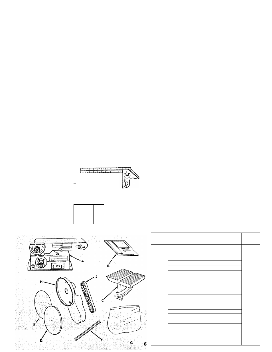
Model 113.226424 Belt and Disc Sander is shipped
complete in one carton.
Separate all parts from packing materials and
check each item with illustration and “Table of
Loose Parts.” Make certain all items are account
ed for, before discarding any packing material.
If any parts are missing, do not attempt to
assemble the Belt and Disc Sander, plug in the
power cord, or turn the switch on until the miss
ing parts are obtained and installed correctly,
WARNING: FOR YOUR OWN SAFETY, NEVER
CONNECT PLUG TO POWER SOURCE OUTLET
UNTIL ALL ASSEMBLY STEPS ARE COMPLETE
and
UNTIL YOU HAVE READ AND UNDER
STOOD THE ENTIRE OWNERS MANUAL.
ITEM
TABLE OF LOOSE PARTS
QTY.
A
Belt and Disc Sander Assembly . , .
1
B
Owner’s Manual ..............................
1
c
Table Assembly...............................
1
D
Sanding Plate .................................
1
E
Sanding Disc....................................
1
F
Table Support Rod ..........................
1
G
Bag Assembly Part
#507771 ...........
Contain ing the following parts;
1
Clamp-Bolt.......................................
Switch, Key......................................
1
Screw Soc. Set 5/16-24X3/8............
1
Wrench, Hex “L” 1/8 ........................
1
Backstop..........................................
Washer, 1/4"....................................
1 r
Bolt, Hex 1/4-20X1/2........................
1
Setscrew 1 /4-20X1/4" ....................
1
Screw 1/4-20X1-3/4"........................
1
Lockwasher 1/4" .............................
1
H
Pulley Cover ...................................
1
:
Timing Belt ......................................
1