Sears 113.299131 User Manual
Page 15
Attention! The text in this document has been recognized automatically. To view the original document, you can use the "Original mode".
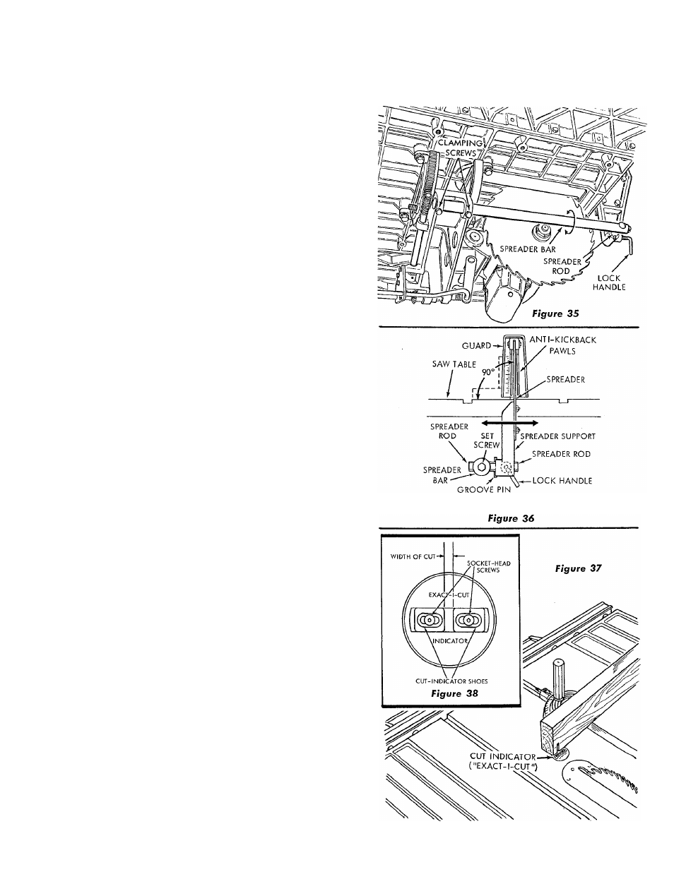
(2) Place a square against the spreader and saw
table top. (See figure 36.) If the spreader bar
is not positioned at 90° with the table, loosen
the two clamping screws (figure 35) and rotate
the spreader bar until the spreader is square with
the table (figure 36.) Tighten the two clamp
ing screws (figure 35) and recheck to make sure
tightening the screws did not change the adjust
ment. More than one trial may be required.
(3) Sight along the spreader and saw blade to check'
for alignmen^. An alternate method is to hold a
straightedge against each side of saw blade and
notice whether or not the spreader is centered
in the gap thus formed between the straightedges.
(4) If the spreader is too far to the right or left, loosen
the hex-head set screw in outer end of spreader
bar and slide the spreader rod in or out of the
hole in the spreader bar until correct alignment
is obtained.
(5) Rotate the plastic guard down into operating
position.
(
6
) For safety and to minimize kickbacks, the blade
guard and spreader must always be in place for
all thru-sawing operations. The spreader must
always be kept in proper alignment with the saw
blade so the spreader doesn't prevent pushing
the work past the blade. The blade guard will
help to prevent sawdust and splinters from being
thrown upward.
(7) To remove the blade guard and spreader, loosen
the lock handle and slide it off. Do not disturb
the spreader rod.
CAUTION: Use extra care whenever the
blade guard is removed for operations in
cluding Dado and Molding.
8. Adjust the Exact-I-Cut Indicator.
(See figures 37 and 38.)
The cut indicator ("Exact-I-Cut") located a few inches
ahead of the saw blade, enables the operator to deter
mine precisely where the cut in a particular board will
occur, provided the cut indicator shoes have been cor
rectly positioned. It should be checked and adjusted (if
necessary) as follows:
a. Position the saw blade in the 90° position (0° on
tilt scale), by loosening the clamp knob and rotating
the tilt crank counterclockwise until it will rotate no
farther. Tighten the clamp knob.
b. With the saw running, place a straight board (pref
erably hardwood) against the miter gauge and hold
it securely in the miter gauge.
c. Make a small cut and pull the miter gauge back until
the cut is directly on the "Exact-I-Cut". (See figure
37.) If both cut-indicator shoes are aligned with the
edges of the cut, no adjustment is required. If not
aligned, loosen the two socket, flat-head screws with
a 1/16 inch hex-”L" wrench and slide the cut indi
cator shoes laterally until the edge of each shoe is
aligned with its respective edge of the cut in the
board. (See figure 38.) Tighten both screws and
recheck for accuracy of the adjustment.
VIEW FROM REAR OF SAW
15