Grounding the generator, Instaljjng wheel kit, Acaution – Sears 919.329150 User Manual
Page 11
Attention! The text in this document has been recognized automatically. To view the original document, you can use the "Original mode".
NOTE; Мак* вше r«d battety boots cover
positive bsttery cable tenninala at batteiy and
aoluiold
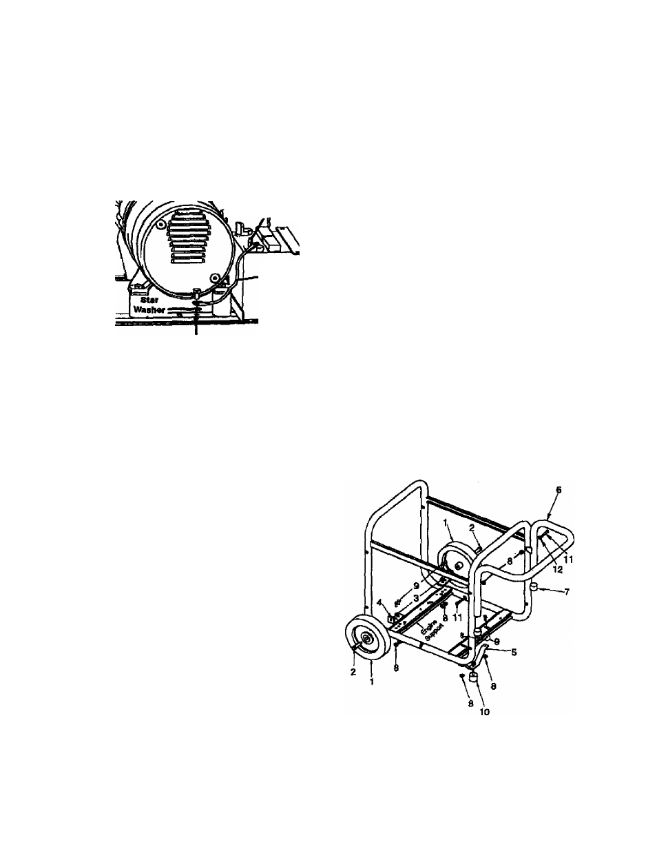
Attach one end of the negative {bladd cable to the
negative (-■) terminal on the battery.
Attach the other end of the negative (blaoK) cable
to the frame as shown. Install the star washer
between the cable and the frame.
IMPOATANT See Caution on page 10
before assembling battery.
H Negattve Battery
Cable cenrwetten
Negative
(•) Battery
Cable
(-) Negative Battery Cable Cennectton
GROUNDING THE GENERATOR
A grounding lug is suppHed with the generator for use
when required by local electrical orcHnances. Refer to
article 250 of the National Eleoirical Code to clarify
any needed grounding information. Vour local electric
company or a certified electrician should be able to
help you with this information.
Groundmg Lug.
NOTE; tfeur engine is already grounded to the frame
by a grounding strap.
INSTALJJNG WHEEL KIT
The Craftsman Wheel Kit was designed to greatly
Improve the ponablllty of your generator.
ACAUTION
I
Dmin gas and oU before
assembing the portability
kit. Failure to do so will cause damage to the
engine.
NOTE: Always follow state regulations for proper oil
disposal.
■ Place generator or? level ground; drain all gas and
oil from the engine {see engine manual for correct
procedure).
• Places 1'thick X V square piece of wood on the
ground in front of the engine. With the help of
another person, tilt the genwator and test the
reooll starter on the wood. NOTE; This will support
the gasoline engine during assembly and make
assembly easier.
Place a handle cap (7) onto each end of handle
prior to Installation.
The handle should be installed on the electrical
outlet er>d of the generator. Place one washer (12)
on long capscrews (11). Align the handle brack
ets with the upper holes pre-drilled in the gerwra-
tor frame. Place mentioned screws through frame
and handle brackets. Secure with lock nuts
(8) and tighten.
Locate the engine support. Place one wheel
bracket (4) on top of support as shown in illustra
tion. Align with the prs-drilled holes in support.
Place 2 cap screws (9) through holes In bracket
and support. Secure with 2 lock nuts (8) and
tighten.
Insert one shoulder bolt (2) Into wheel (1). Insert
threaded end of bolt through wheel br^et,
secure with lock nut (3) and lighten. NOTE; The
wheel will net rub frame If Installed properly,
Repeat the ^love steps for the opposite side.
Insert the threaded stud of rubber foot (10)
through the middle hole of the foot brocket (5).
Secure with lock nut (S) and tighten.
Locate the support under the electrical outlet end
of the generator. Position foot bracket (5), with
rubber foot Installed, under the support and align
the holes In the foot bracket (5) with the slots in
the support. Place one cap screw (9) through each
slot In the support and the holes in the foot
bracket Secure with the lock nuts (8) and tighten.
Once completed, the wheel kit is ready for use.
n -ENQ
ОШ» itaKowaiAo