Pin figure 10 – Sears 917.249391 User Manual
Page 8
Attention! The text in this document has been recognized automatically. To view the original document, you can use the "Original mode".
PIN
FIGURE 10
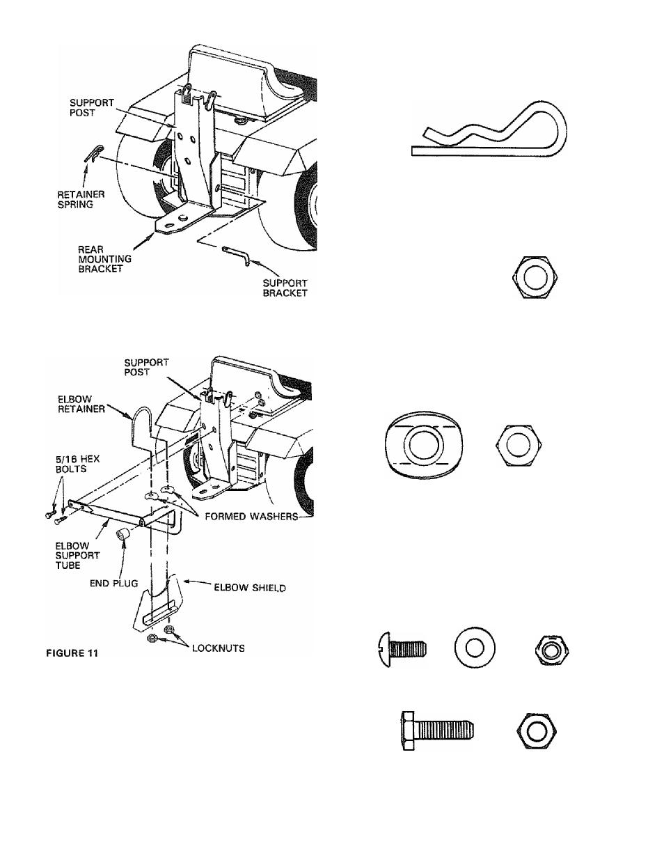
5.
A ssem ble the support post to the rear m ounting
bracket (Fig. 10} using support bracket pin and re
tainer spring. R etainer spring show n full size below .
S upport post, latch pin and retainer spring furnish
ed w ith bagger.
6
.
8
M ount elbow support tube to support past (Fig. 11}
using: tw o 5/16 hex bolts and tw o 5/16 locknuts
(show n full size below }. N O TE : P osition elbow sup
port tube
as show n in Fig. 11. Tighten securely.
E lbow support tube and hardw are furnished w ith
Instaii end plug (Fig. 7 V on elbow support tube. E nd
plug furnished w ith bagger.
M ount the elbow retainer and the elbow shield to
the elbow support tube (Fig. 11) using: tw o form
ed w ashers and tw o 5/16 iocknuts (show n full size
below }.
N O TE :
D o
not
tighten.
Elbow
retainer,
elbow shield and hardw are furnished w ith bagger.
9.
S lide
elbow
through
elbow
retainer
(Fig.
12-Inset).
S ecure
elbow
to
eibow
retainer
using:
tw o
clips,
tw o
screw s,
tw o
w ashers
and
tw o
acorn
nuts.
N O TE: M ount clips in holes located 2
-
1/2” from
edge
of
elbow .
H ardw are
show n
full
size
below .
H eads of screw s and flat w ashers m ount to the In
side of elbow . P osition clips w ith closed end of clip
facing tube opening as show n in Fig. 12 - Inset.
Tighten
securely.
N O TE :
Tighten
hardw are
assem bled in step 8. E lbow and hardw are furnish
ed w ith grass catcher.
1 0. Flip seat forw ard.