Sears 917.249391 User Manual
Page 5
Attention! The text in this document has been recognized automatically. To view the original document, you can use the "Original mode".
3.
M ove
gear
shift
lever
(Fig.
2}
to
"N E U TR A L"
position ^
4.
P lace parking brake IFig. 2) in "EN G A G E D " posi
tion. R aise parking brake lever and hold in "E N
G A G E D " position. R elease clutch-brake pedal.
5.
D isengage m ow er blade clutch lever (Fig. 2 - Inset}.
DISCOWNECT THE SPARK PLUG WIRE{S)
FROM THE SPARK PLUG(S| AND KEEP
WIREIS! AWAY FROM THE PLUGiSJ TO
PREVENT INJURY FROM ACCIDENTAL
STARTING,
6.
R em ove m ow er from tractor. R efer to "To R em ove
M ow er"
in
your
tractor
ow ners
m anual.
Turn
the
m ow er upside dow n.
7.
U sing
a
9/16"
w rench
rem ove
the
bolts,
lockw ashers
and
w ashers
securing
the
m ow er
blades
to
the
m andrel
assem blies.
S ave
hardw are
for later use w hen m ow er is used w ithout grass
catcher,
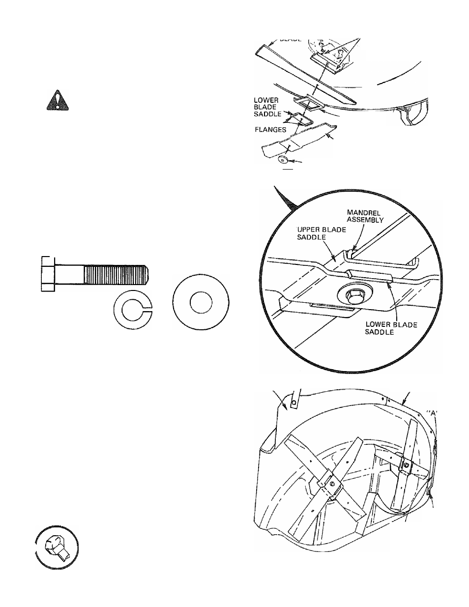
8.
M ount grass catcher blades, low er blade saddles,
upper blade saddles and m ow er blades to m andrel
assem blies (Fig, 3) using; tw o 3/8 - 24 x 1 - 3/4
hex bolts gr. 5, tw o lockw ashers and tw o w ashers
(show n full size below }. G rass catcher blades, low er
blade
saddles,
upper
blade
saddles
and
hardw are
furnished w ith grass catcher.
a. For ease of assem bly, turn m ow er upside daw n,
b.
R eturn m ow er blade (Fig, 3} to original position
against m andrel assem bly,
c.
P lace upper blade saddle and low er blade sad
dle
(Fig.
3)
on
m ow er
blade.
N O TE:
P osition
flanges as show n in Fig, 3,
d.
P lace grass catcher blade in low er blade saddle.
N O TE: B e sure pointed edges of grass catcher
blade are facing upw ard {Fig. 3).
e.
S ecure grass catcher blade assem bly to m andrel
assem bly
using
hex
bolt,
iockw asher
and
w asher
(Fig.
3),Tighten
securely.
N O TE :
Low er
blade saddle m ust be seated inside upper blade
saddle (Fig. 3
-
Inset}. R epeat procedure for other
blade.
A
ALWAYS USE GRADE S HEAT TREATED
BOLTS TO ATTACH BLADES. CHECK
BOLTS IN BLADES OCCASIONALLY TO
MAKE SURE BOLTS ARE TIGHT. TORQUE
BOLTS
27 -
35 FT. LBS.
A GRADE 5 HEAT TREATED BOLT CAN BE
IDENTIFIED BY THREE LINES INDICATED
ON THE BOLT HEAD AS SHOWN AT LEFT.
9.
U sing a 1/2" w rench rem ove hardw are "A " & "B "
(Fig.
4}
securing
L.H .
runner
to
m ow er
housing.
H ardw are m ay be discarded.
MOWER ,,
. Rf AnC .
MANDREL
ASSEMBLY
UPPER BLADE
SADDLE
GRASS
CATCHER
BLADE
^ 'WASHER
.—
^^^LGCKWASHER
Ey**—HEX BOLT - GR. 5
FIGURES
R.H. BAFFLE
L.H. BAFFLE
"B "
LH. RUNNER
FIGURE 4