Controls and adjustments, On-off switch, Depth stop adjustment – Sears 149.213340 User Manual
Page 8: Spindle return spring adjustment, Table adjustment
Attention! The text in this document has been recognized automatically. To view the original document, you can use the "Original mode".
CONTROLS AND ADJUSTMENTS
A
WARNING:
M
ake
sure
switch
is
in
OFF
position
AND POWER CORO IS UNPLUGGED BEFORE PERFORMING
CHECKS, ADJUSTMENTS, OH SETUP PROCEDURES.
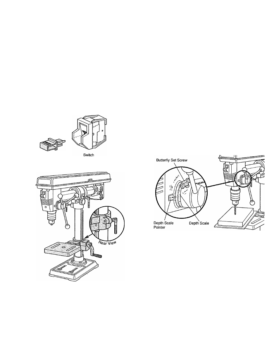
On-Off Switch
The ON-OFF switch (REF 59) is located on front of Drill Head
and has operating positions clearly marked. Push switch up
to turn too! ON and down to turn it OFF. The switch has a
Switch Key (REF 60) that, when removed, allows switch to
be locked in OFF position. To activate locking feature, push
switch to OFF and pull Switch Key out of switch..
Switch Key
2. Table Rotation - To rotate table, first loosen Lock Handle.
The table can be rotated from side to side or completely
out from under Spindle Shaft to allow work surface on
base to support workpiece.
Depth Stop Adjustment
When it is desirable to drill holes to an exact depth, the built-
in depth stop can be set
1.
With Radial Drill Press turned OFF, adjust table height
until drill bit barely touches workpiece at spot to be drilled,
and lock into position.
2.
Loosen Depth Stop Butterfly Set Screw (REF 36) and
rotate Depth Gauge Assembly (REF 35) until desired drill
depth on Scale aligns with Pointer on Spindle Housing
(REF 25). Tighten Butterfly Set Screw.
Spindle Return Spring Adjustment
An automatic spindle Return Spring (REF 28) is installed in
Drill Head to return spindle to full up position. This spring
was preset at the factory and should not be readjusted
unless absolutely necessary. Adjust Return Spring as fol
lows:
Table Adjustment
1. Table Height - To raise or lower Table, loosen Lock
Handle on back of Table Bracket. Crank Lift Handle to
raise or lower Table, then lock position with Lock Handle.
1.
Loosen two Nuts (REF 29
&
30) on side of Spring
Assembly (REF 28) about 1/4". NOTE: Do not remove
these nuts from Feed Shaft (REF 34}„
2.
Hold Spring Assembly firmly and pull it out away from
side of Drill Head. Rotate Spring Assembly until next
notch engages with cast tab on side of Drilf head.