Assembly – Sears 149.213340 User Manual
Page 6
Attention! The text in this document has been recognized automatically. To view the original document, you can use the "Original mode".
ASSEMBLY
A
A
WARNING: F
ob
vour
own
safety
,
never
connect
THE R
adial
D
rill
P
ress
to
a
power
source
until
ALL ASSEMBLY STEPS ARE COMPLETE, AND YOU HAVE
READ AND UNDERSTOOD SAFETY AND OPERATIONAL
INSTBUCTtONS.
CAUTION: Do
not
allow
brake
fluids
,
gasoline
,
PENETRATING OILS, ETC., TO COME IN CONTACT WITH
PLASTIC PARTS. T
hese
solutions
contain
chemicals
THAT CAN DAMAGE AND/OR DESTROY PLASTICS.
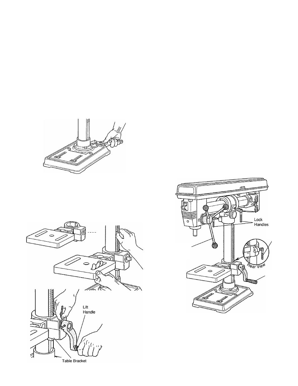
1. Assemble Column and Flange Assembly (REF 4) to Base
Assembly (REF 1) using four 8mm x 25mm bolls (REF 5).
2
Slide Worm Pinion (REF 9) into Table Bracket (REF 6) until
shaft extends from hole and teeth engage with Table Lift
Gear (REF 7) Lower Verlica! Rack (REF 15) into Table
------- .
Bracket making sure that the teeth are engaged In the
Table Lift Gear inside bracket Slide rack and bracket
assembly onto column until angled end at bottom of rack
fits into top of column flange
3
Place Lift Handle (REF 10) on Worm Pinion Shaft extending
from Table Bracket Align flat on pinion shaft with set
screw (REF 11) and tighten
NOTE: Before installing drill head assembly, find a per
manent
focation
for
radial
drill press
and
fasten base
down using Carriage Bolts (REF 96} and Wing Nuts (REF
97)
provided.
BE
SURE
BOLTS
PASS
ENTIRELY
THROUGH
MOUNTING
SURFACE.
(See
Installing
Radial
Drill Press section on page 7.)
4. Place Lock Shoe (REF 88) from loose parts bag into cast
pocket in Column Head Assembly (REF 83) then slide
Column Head Assembly with Drill Head Assembly down
onto Column as shown
Be very careful to hold Lock Shoe
in place during assembly to prevent it from falling down
inside column.
Be sure to engage Vertical Rack with angle
on bottom of Column Head, Drill head should rotate freely
around column
Lock
Handle
Handle
Bar
Lift
Handle
5„
6,,
Attach one Lock Handle (REF 14) to Table Bracket and
two Lock Handles to Column Head,
Attach three Handle Bars (REF 37) into threaded holes
on head of Feed Shaft Assembly (REF 34).