Tools required for assembly, To remove pressure washer from carton, How to set up your pressure washer – Sears 580.75151 User Manual
Page 7: Assembly
Attention! The text in this document has been recognized automatically. To view the original document, you can use the "Original mode".
ASSEMBLY
Read these Instructions and Operator’s Manual in its en
tirety before you attempt to assemble or operate your new
high pressure washer. Your high pressure washer has, for
■fHCi FTÍA
c
I
s
AH
AYf'Anf fKACA
II Iw PI IwOI- ii/Cll I |i Mvi'd 1 CUCPwCv 11 iKiifi Cit It Iw I €3.\t*Lvri y | N7AvrN7|n« I- M IMOw
parts left unassembled. Before you can operate your new
high pressure washer, you must assemble the wheel kit and
properly connect the high pressure hose.
IF YOU HAVE ANY PROBLEMS WITH THE ASSEMBLY
OF YOUR PRESSURE WASHER, PLEASE CALL THE
PRESSURE WASHER HELPLINE AT 1-800-222-3136.
TOOLS REQUIRED FOR ASSEMBLY
■> Mallet
»
2 adjustable wrenches OR the following wrenches:
B 5/16“ (8mm) combination wrench
»
1 /2" (13mm) combination wrench
»
S/8" (16mm) combination wrench
B 11/16" (18mm) combination wrench
B 7/8" (22mm) combination wrench
B 15/16" (24mm) combination wrench
TO REMOVE PRESSURE WASHER FROM
CARTON
B Remove two boxes marked "PARTS iNSIDE" and re
move the parts contained in both boxes.
B Remove unit with one hand under pump and one hand
under recoil starter
Refer to Page 6, "Contents of Hardware Pack” for an
Illustrated listing of ali the items included with your pressure
washer. Become familiar with each piece before assem
bling the pressure washer. Check all contents against the
illustrations on Page 6. If any parts are missing or dam
aged, call the Pressure Washer Helpline at 1-800-222
3136,
HOW TO SET UP YOUR PRESSURE WASHER
TO
IN*чTДt I THF WHFFI KIT
II Ч W I #%I
hb
K
n
>
i
I |Т11и« KV 11Км1м*1м|' ^41 I
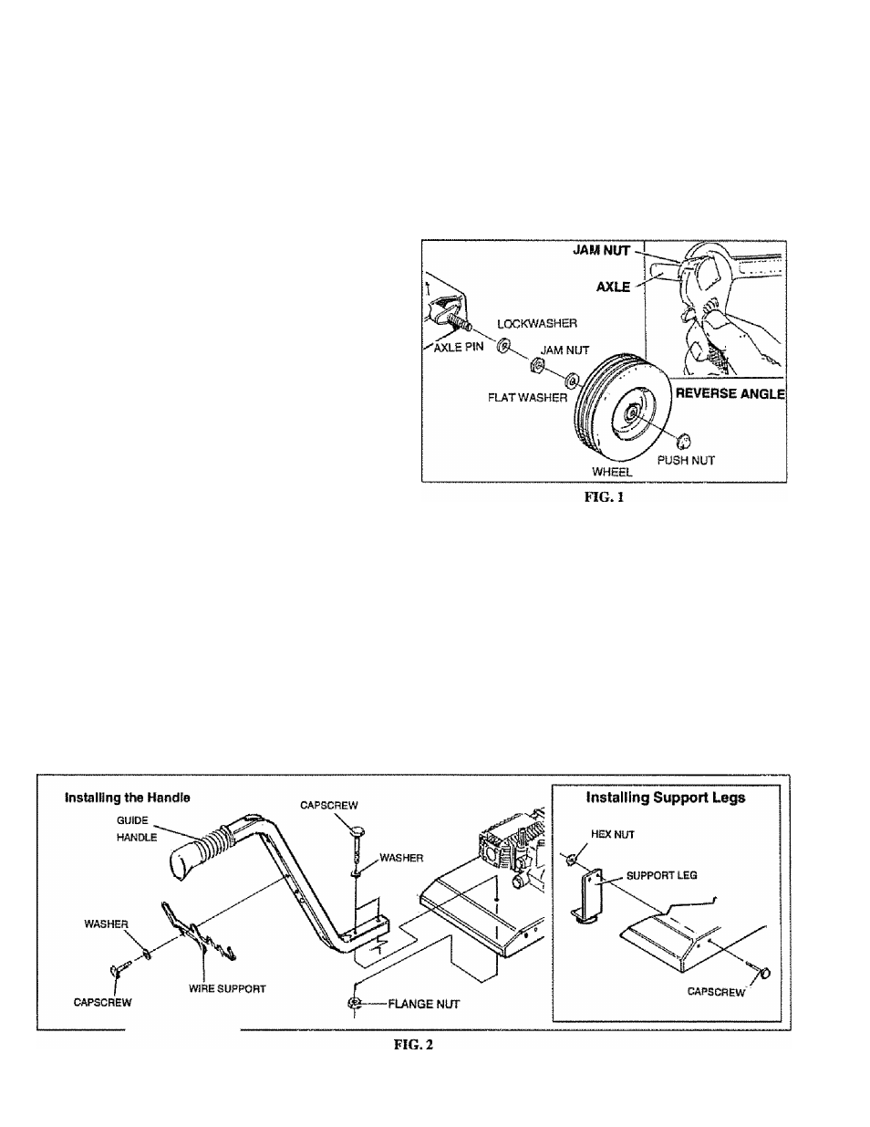
Installing the wheel kit requires the tools listed, the guide
handle and items included in the parts carton.
e Prop up fte engine end of the main unit, This will allow
you to slip each axie pin into the holes provided on the
side of the base (Fig. 1).
With the axle pin inserted inside the base, grip the end
of the axle pin as shown with an adjustable or 15/16"
combination wrench. This will keep axle from spinning
as you fasten axle to the base with a 5/8“ lock washer,
a 5/8"-18 JAM nut, and an M12 flat washer.
Place wheels on the axles so the rib side of hub is
against mounting base.
Retain each wheel to Its axle pin by tapping a push nut
onto end of axle with a maliet.
Attach support legs to base as shown in Fig, 2 with MB
X 20mm hex head capscrews and flange lock nuts.
Tighten with 13mm or 1/2-inch wrench on each fas
tener. Be sure legs are straight when you are finished.
Attach the guide handle to the base as shown in Fig. 2
with two M8 X 40mm hex head capscrews, two MB
washere and two flange nuts.