Service and adjustments – Sears 917.25147 User Manual
Page 21
Attention! The text in this document has been recognized automatically. To view the original document, you can use the "Original mode".
SERVICE AND ADJUSTMENTS
TO LEVEL MOWER HOUSING
Adjust the mower while tractor is parked on level ground or
driveway. Make sure tires are properly inflated (See
“PRODUCT SPECIFICATIONS” on page 3 of this manual).
If tires are over or underinflated, you will not properly adjust
your mower.
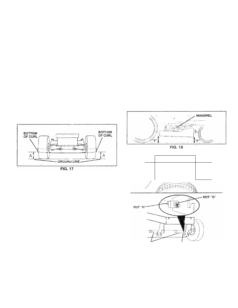
SIDE-TO-SIDE ADJUSTMENT (See Figs. 16 and 17}
® Raise mower to its highest position.
* Measure height from bottom of deck curi to ground
ievel at front corners of mower. Distance “A” on both
sides of mower shouid be the same, .
® If adjustment is necessary, make adjustment on one'
side of mower only.
« . To raise one side of mower, tighten lift link ad;’istment
nut on that side.
.
® To lower one side of mower, ioosen lift link adjustment
. nut on that side.
.
NOTE: Each full turn of adjustment nut will change mower
height about 3/16".
« Recheck measurements after adjusting.
FRCNT-TC-BACK ADJUSTMENT (See Figs. 18 and 19) -
IMPORTANT:
DECK
MUST
BE
LEVEL
SIDE-TO-SIDE.
IF
THE
FOLLOWING
FRONT-TO-BACK
ADJUSTMENT
IS
NECESSARY. BE SURE TO ADJUST BOTH FRONT LINKS
EQUALLY SO MOWER WILL SiAY LEVEL SIDE-TO-SIDE.
To obtain the best cutting results, the mower housing
should be adjusted so the front is approximately 1 /8" to 1 /2"
lower than the rear when the mower is m its highest
position.
Check adjustment on right side of tractor. Measure dis
tance “F” directly in front of and behind the mandrel at
bottom edge of mower housing as shown.
*
Before making any necessary adjustments, check that
both front links are equal in length,
» If links are not equal in length, adjust one link to same
length as other link. ■
*
T0 iowerfront of mower housing, loosen nut “G” on both
front links an equal number of turns.
» When distance T”l.s .r.j Jv V2" lower at front than rear,
tighten nut "H” against trunnion on both front links.
® To raise front of mower housing, loosen nut “H” from
trunnion on both front links. Tighten nut “G” on both
front links an equal number of turns.
When distance “F” is ' '3” to 7/2" lower at fro
3.3
tighten nut "H” against trunnion on both front links.
NOTE: Each full turn of nut “G" will change dim. “F” by
approximately 3/8“.
® Recheck side-to-side adjustment.
BOTH FRONT LINKS MUST BE EQUAL IN LENGTH
/'fl
1 U 1 1
/
II
1.. - ■ :.
3. .fc-ad
/ C
t
)
FRONT
LINKS
T
r u n n i o n
FIG. 19
21