Start-up – Carrier 19DG User Manual
Page 5
Attention! The text in this document has been recognized automatically. To view the original document, you can use the "Original mode".
8. Wi’th“OIL PUMP button depressed, alternately
stop and restart chilled water and condenser
water pumps. SAFETY CIRCUIT and LOAD
RECYCLE lights should go out as each pump
stops. (Continuous operation of oil pump is
unnecessary during these checks.)
CONTROL LIGHTS
□
OFF
■ ON
□
□
□
■
■
□
□
□
a
■
■
n
■
■
■
n
□
■
■
■
□
□
□
■
□
■
9
10
II
12
13
14
ON-STOP
START
OIL PUMP
POWER
SAFETY CIRCUIT
LOAD RECYCLE
PROGRAM TIMER
9. Shut off water pumps. Release OIL PUMP
button. Press ON-STOP button (hght goes
out). Replace tagged wire on terminal
10. Press ON-STOP button (hght goes on).
11. Press machine START button (motor leads
disconnected).
12. Oil pump starts within 30 seconds.
13. Compressor motor start contacts will close 30
seconds later. Starter will transfer to run
condition 30 to 60 seconds after starter is
energized.
14. Open oil pump main disconnect. Starter must
de-energize. OIL PUMP hght will remain on for
approximately 30 seconds.
15. OIL PUMP light goes out.
16. Close oil pump disconnect. In approximately
15 minutes, the program timer will complete
the antirecycle portion of its cycle and the
machine is ready to restart.
17. Remove all power and reconnect motor leads.
Restore power.
Purge
— Place the purge operating valves (Fig. 1) in
“Normal-Automatic” position as indicated in oper
ation no. 1 on the purge valve operation plate
(item 17, Fig. 1). Operate the purge pump momen
tarily by placing the purge switch in “Manual”
position; then place purge switch in “Auto.”
position.
START-UP
Preliminary Checks
1. Power on to main circuit breaker, control
circuit, water pumps and tower fan.
2. Cooling tower water level.
3. Oil reservoir level.
4. Oil reservoir temperature 145 F or warmer.
5. Oil cooler plug cock (Fig. 1) cracked open, and
any other valves in oil cooler line fully open.
6. Refrigerant at proper level.
7. Valves in chilled water and condenser water
circuits open and water circulating properly. Do
not permit water above 100 F to flow thru
cooler.
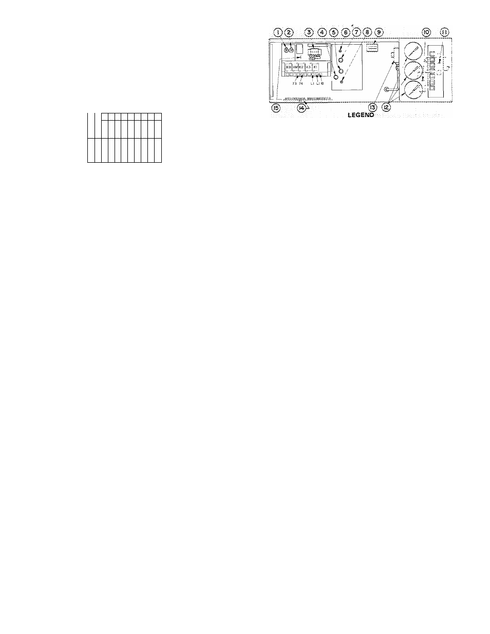
1 — Searing High-Temperature C'Jtout iXtenua! Reset)
2 — Motor tiigh-Temperafure Cutout (Mapua! Reset)
3 — Prograrr. Timet
4— Capacity Comrot Switch
5 — &tectric3i Demarto Acfjusimeot
6 —Throttfe Rarige Aojustmem
7—Thermostat iChilieci’Water)
5— Motor Current Calibration
9-eiaP38d-Time(ncl!cator
TO— Low Oil Pressure Cutout
1 — Vane-t^iose Oii Pressure Switch
12 — Pressure G ages
■J3 — Conclertser HighPressurs Cutout (Manual Reset)
■J4. _ Terminal Strip (PielcJ Connections)
15 — Retey Ntocfule
Fig. 3— Control Center
COMPRESSOR ROTATION Set capacity con
trol switch (Fig. 3) to “Hold”. Press machine
ON-STOP and START buttons. As soon as motor
starts to turn, press machine ON-STOP button.
Check motor rotation thru sight glass in motor end
bell (Fig. 1). Motor rotation must be clockwise
when viewed from motor end. If not, reverse any 2
of 3 power leads coming into motor starter and
recheck rotation.
COMPRESSOR OPERATION ~ Press machine
ON-STOP and START buttons and let compressor
come up to speed. Press machine ON-STOP button
and listen for any unusual sounds coming from the
compressor and transmission housing as the com
pressor coasts to a stop.
The program timer prevents rapid recycling of
the compressor and allows restart 15 minutes after
stop.
Checking Safety Control Settings
While performing these checks, carefully
monitor chilled water temperature to prevent
freeze-up. Protection by safety cotrols cannot
be assumed until all settings have been con- .
firmed as follows.
Open main disconnect (all power off to starter
and controls). Set capacity control switch to
“Hold”. Place a clamp-on ammeter on one of the 3
starter leads. Install jumpers between 40 and [^,
and between (l^ and jj_. Close disconnect(s);
start compressor and check oil pressure and tem
perature (Pig. 1). With compressor running,
manually operate the guide vanes with the capacity
control switch. Do not exceed 100% of full load
amperage.
1. Check controls 1,2 and 3 as indicated in T|^ 2.
2.
Stop machine; open disconnect(s); remove
jumpers and check controls 4, 5 and 6 as
indicated in Table 2.