Carrier 19DG User Manual
Page 4
Attention! The text in this document has been recognized automatically. To view the original document, you can use the "Original mode".
Oil Heater
— Energize’ the oil heater to minimize
absorption of refrigerant by the oil. An indicator
light (Fig. 1) goes on when the oil heater is
energized. Set the oil heater thermostat to main
tain a minimum oil reservoir temperature of 145 F
at shutdown.
Charging Refrigerant
— Proceed as follows.
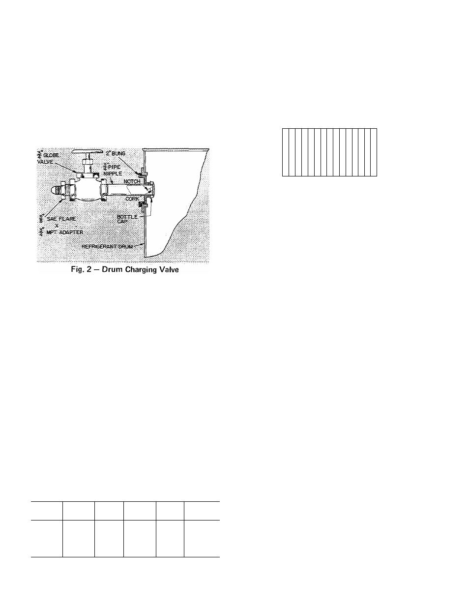
1. Install a charging valve on the 3/4-m. drum
opening as shown in Fig. 2. When the 3/4-in.
pipe nipple is screwed in, the nipple forces the
bottle cap off its seat.
2. Connect a short piece of plastic hose or copper
tubing from drum valve to the cooler charging
valve located beside the float chamber (Fig. 1).
3.
Circulate chilled water during the charging
process.
4.
At a vacuum of IS in. Hg or greater, liquid
Refrigerant 1 i will flash mto gas and may
cause tube freeze-ap. If machine vacuum is
18 in. Hg or greater, keep refrigerant drum
upright, open valves and admut refrigerant to
cooler as a gas until machine vacuum is ies.s =
than 18 m. Kg.
5. The refrigerant supplied with the machine is in
excess of that required for initial charging.
Charge only that amount shown in Table 1 The
machine under vacuum will draw refrigerant
from the drum.
6. After the machine has been started, it may be
necessary to adjust the refrigerant charge for
optimum
machine
performance.
Refer
to
Trimming Refrigerant Charge (page 7) for full
load adjustment.
Table 1 — Charging Quantity
SIZE*
WEIGHT
(lb R-11)
SIZE*
WEIGHT
(lb R-11)
SIZE*
WEIGHT
(lb R-11)
19DG11
400
19DG21
525
19DG33
760
19DG13
400
19DG23
550
19DG35
800
19DG15
425
19DG25
575
19DG36
925
19DG17
450
19DG27
575
19DG37
985
19DG20
525
19DG31
725
19DG39
960
Check Operation of Safety Controls
— As checks
are made, the control panel lights should appear as
indicated.
1. Open main disconnect (all power off to starter
and controls). Then disconnect main motor
leads in starter.
2. Provide control circuit power.
CONTROL LIGHTS
□ OFF
□
□
■
□
■
■
■
■
□
□
□
□
□
□
□
□
□
□
□
a
n
■
□
■
□
■
■
■
■
■
■
■
□
□
■
□
□
■
□
□
□
□
■
□
□
■
□
□
□
□
□
□
□
□
□
□
1
2
3
4
5
6
7
8
ON-STOP
START
OIL PUMP
POWER
SAFETY CIRCUIT
LOAD RECYCLE
PROGRAM TIMER
*Unishe(i Size
• Sec lower right corner of machine identification
plate (Fig 1)
3. Press ON-STOP button (light goes on). If
SAFETY CIRCUIT light does not go on, check
resets on condenser high-pressure safety, low-
refrigerant safety, bearing and motor high-
temperature circuit breakers and compressor
overloads in starter. Check 3-amp fuse in
control center.
If SAFETY CIRCUIT light goes on but LOAD
RECYCLE light stays off, check the chilled
water recycle switch (Auto.-Reset).
If both lights go on, manually trip and reset
motor and bearing high-temperature circuit
breakers, compressor motor overloads in
starter, low-refrigerant temperature cutout and
high-condenser cutout to be sure they cut off
the safety light. Tripping the chilled water
recycle switch will cut off the LOAD RE
CYCLE light only.
4.
Press ON-STOP button (light goes out).
Remove and tag gray striped wire running
between terminal [1^ and Vl_ in control
center.
5.
Start chilled water and condenser water
pumps. Press ON-STOP button (light goes on).
6. Press OIL PUMP button for several seconds.
Pump should raise oil pressure to 20-25 psi
differential between pump discharge gage on
control panel and oil reservoir gage. SAFETY
CIRCUIT and LOAD RECYCLE lights should
go on.
7. Release OIL PUMP button. SAFETY CIR
CUIT and LOAD RECYCLE lights should go
out.