Table 3 — checking safety controls (cont), Setting operating controls – Carrier 19EA User Manual
Page 7
Attention! The text in this document has been recognized automatically. To view the original document, you can use the "Original mode".
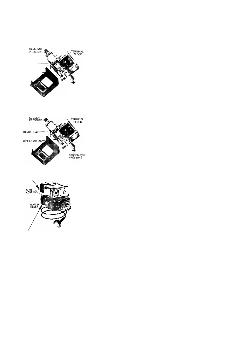
Table 3 — Checking Safety Controls (cont)
SAFETY OR CONTROL DEVICE
3. Low Oil Pressure Cutout (Fig. 3)
RANGE
DIAL ADJUSTMEN1?
REMOVE METAL
COVER
DIFFERENTIAL
OIL
PRESSURE
4. Economizer Cooler Differentia! Pressure
Switch {Fig. 3)
Ù .
i. Condenser High-Pressure Cutout (Fig. 3)
range
adjustment
SCREW
6. Cooler Low-Pressure Cutout (Fig. 3)
RECOMMENDED SETTING
Factory set to cut out at 13 ±1 psi differential Operate oil pump manually
Remove cap and gasket from regulating valve (item 18, Fig 1) Loosen locknut
Turn adjusting screw counterclockwise to lower oil pressure to 12 psi differential
If safety does not trip, turn range dial clockwise until cutout occurs Access to
control is thru knockout at rear of control box
'<7
The economizer-cooler differential pressure switch is factory set to energize the
refrigerant feed control at 10 psid
The condenser high pressure switch is factory set to shut machine down when
condenser pressure reaches 161 ±5 psig Field calibration is not required
Cooler low-pressure switch is factory set at 32 ±2 psig If design suction
temperature is below 36 F, field resetting may be necessary With control power
off (power light out), install jumpers between terminals
and 0 and
between
and
. Set switch to cut out at one degree below design
suction temperature Remove jumpers Restore power
Setting Operating Controls
MOTOR CURRENT CALIBRATION
PROCEDURE
design leaving chilled water temperature and
1. Establish a steady motor cun'ent value for this
calibration.
Open
guide
vanes
manually
(capacity control to “Inc”) until full load
current is reached. Motor current calibration
adjustment (item 1, Fig. 3) may have to be
turned counterclockwise to permit vanes to
open further. Do not exceed 105 percent of
nameplate full load amps
If building load is sufficient to maintain full
load current for a period of time, calibrate at
this condition. With small loads, pull down to
and maintain (capacity control to “Hold”)
calibrate at this condition.
2. Measure motor current at selected condition.
Determine its percentage of full load motor
current.
3. Use this percentage figure to set the electrical
demand adjustment (item 3, Fig. 3) per the
following table:
Percent of Full
Load Motor Current
105
85 or above
65 to 84
45 to 64
below 45
Electrical Demand
Adjustment Setting
1ÜÜ pêrcêrvF ~
80 percent
60 percent
40 percent
Control cannot be
calibrated