Start-up, Service, Refrigerant charging – Carrier 50MH User Manual
Page 5: Lubrication, Condenser, Evaporator, Return air filter
Attention! The text in this document has been recognized automatically. To view the original document, you can use the "Original mode".
#
START-UP
Adjust remote control center as follows:
1. Set selector switch at “Off.”
2. Fan switch at “Auto.” or “Fan.”
3. Turn on main disconnect switch(es) to unit.
4. Set thermostat dial to the desired temperature.
5. Selector switch at “Heat” or “Cool.”
Electric Resistance Heater Operation
— When
thermostat calls for heating, evaporator fan and
heater no. 1 are energized immediately. Remaining
heaters are energized in 30 second intervals. When
thermostat is satisfied, the cycle reverses and
heaters are de-energized in 30-second intervals.
Evaporator fan motor shuts off with last heater.
SERVICE
Table 3 — Service Data
UNIT
50MH003
50MH004
R-22 CHG (Ib-oz)*
3-0
3-11
Refrig Control
TXV
TXV
COMPRESSOR
38GC401404
51YA400524
Type Start
CSR
CSR
Oil Recharge (oz)
45
50
EVAP FAN
Centrifugal — Direct Drive
Rpm
1075 - 950 - 850
Diam (in.)
10
10
Width (in.)
8
8
Nom Cfm
1125
1350
Norn Motor Hp
COND FAN
Propel 1er — Di rect Drive
Rpm
1050
1050
Diam (in.)
18
18
Norn Cfm
2400
2400
Norn Motor Hp
%
ke
CSR — Capacitor Start
* Factory refrigerant charge
REFRIGERANT CHARGING
Refrigerant System is factory charged. When
recharging is necessary, weigh in total charge
indicated in Table 3. Blow any refrigerant
remaining in system before recharging. Standard
1/4-in. Schraeder service connections provided on
high and low sides of refrigerant system for
evacuation and charging.
LUBRICATION
Compressor
contains factory oil charge. Replace oil
when lost. See Table 3 for oil charge. If necessary,
refer to Carrier Standard Service Techniques
Manual, Chapter 1, pg 1-21, for oil recharging
procedure. Use Carrier PP33-1, Texaco Capella B
or Suniso 3G oil.
Fan Motor Bearings
are prelubricated for three
years heavy duty or five years normal duty. When
lubrication is necessary, send motor to authorized
motor repair shop.
CONDENSER
Coil
— Lift or remove unit top cover for access to
condenser coil. Inspect coil periodically. Clean
with brush, vacuum cleaner, low-pressure water,
steam or air.
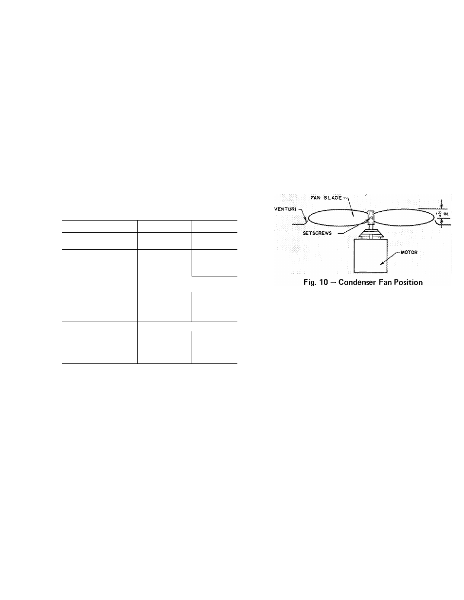
Fan Position
— Required fan position is shown in
Fig. 10. Adjust fan by loosening setscrews and
moving blades up or down.
EVAPORATOR
Coil
— Lift or remove unit top cover for access to
evaporator coil. Inspect coil periodically. Clean
with brush, vacuum cleaner or low-pressure air.
CONDENSATE DRAIN — Clean condensate drain
trap with bottle brush, then flush condensate pan
beneath evaporator coil with clean water. Ensure
water flows freely thru condensate drain.
Evaporator Fan Wheel
should be centered in fan
housing. To adjust, loosen setscrews holding fan to
rhotor shaft. Adjust fan and retighten setscrews.
EVAPORATOR PAN REMOVAL - Disconnect
fan motor wiring. Remove two fan housing sheet
metal screws shown in Pig. 6 and slide out
complete fan and motor assembly.
RETURN AIR FILTER
Clean filter a minimum of twice yearly. Flush
permanent-type filter with hot water, steam or
soak in mild solution of soap or detergent and
water. Allow filters to dry and replace. Refer to
filter manufacturer’s instructions, as required, for
other types of filters.
«