Frl ri mi – Carrier 50MH User Manual
Page 3
Attention! The text in this document has been recognized automatically. To view the original document, you can use the "Original mode".
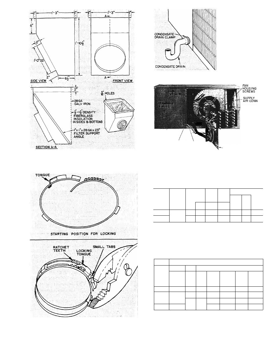
Fig. 3 — Minimum Dimensions Return Air
Filter Box
fRl
RI
mi
Fig. 5 — Condensate Drain Connection
HEATER
INSTALLATION
OPENING
LINE POWER
LEADS FROM
HEATER
CONTROL
WIRING
RECEPTACLE
CONTROL
LEADS
FROM HEATER
ELECTRIC HEATER
ASSEMBLY
Fig. 6 — Electric Resistance Heater Installation
i.0Ci(fN6
CLA«P IN LOCKIXS POSJTiO«
Fig. 4 — Condensate Drain Clamp
ELECTRICAL DATA AND WIRING
Table 1 — Unit Electrical Data
MODEL
50MH
VOLTS/
PH
EVAP
FAN
COND
FAN
BRANCH CKT
COMPR
Wire
Size
(AWG)
Max
Ft
Wire
Fuse
Amps
LRA
FLA
FLA
FLA
003
230/1
86.0
19.5
3.4
1 1
10
30
30
004
93 0
20 0
3 4
1 1
10
30
30
LRA — Locked Rotor Amps
FLA — Full Load Amps
NOTE:
Motors and controls will operate satisfactorily 10% above and 10%
below unit voltage. Control circuit voltage is 24 volts on all units.
Table 2 — Electric Resistance Heater Data
ELECTRIC HEATER
UNIT
50MH
Branch Circuit
Volts/
Ph
KW
No.
FLA
(ea)
Wire
Size
(AWG)
Max
Ft
Wire
Fuse
Amps
5
1
20.8
10
30
30
003
&
004
240/1
10
1
41.7
6
30
50
15
2
20 8
10
30
30
41 7
6
30
50
Wiring —
Field wiring must comply with local and
national codes. Install a branch circuit fused
disconnect of adequate size to handle unit starting
current. Provide a separate fused disconnect for