Fig. 7 — line power connections, Fig. 9 — typical system wiring diagram, 10 kw – Carrier 50MH User Manual
Page 4
Attention! The text in this document has been recognized automatically. To view the original document, you can use the "Original mode".
each electric resistance heater. Voltage to unit
during operation must be within ± 10% of voltage
range indicated on nameplate.
Failure due to operation of unit on improper
line voltage constitutes abuse ana is not covered
by Carrier Warranty.
LINE POWER — Bring line power leads from fused
disconnect thru hole provided (Fig. 1) into high
voltage section of control box. Connect line power
leads to Terminals 1 and 2 on Terminal Board 1.
See label diagram and Fig. 7. Aluminum field
wiring may be used when splice connected to
copper pigtails from unit with approved copper to
aluminum splice connectors.
Accessory Electric Fleater(s) — Connect line power
leads from fused disconnect(s) to Terminal Board 2
as shown in Fig. 7. Extend power leads (supplied
with electric heater) from heater thru fan section
and thru hole provided into high voltage section of
control box. Connect leads to Terminal Board 2
(Fig. 6 and 7).
THERMOSTAT’
TERMINAL
BOARD 3
TO
HEATER
FD
TO (-
HEATER <
FD 1-
RED
BLK
—
”0—[
a
F
YEL
—
-0—0-
BLU
)
(2
TO
10 Kw
HEATER
1
TO
> 5KW
1 HEATER
FD — Fused Disconnect
______Field Wiring
______Factory-Supplied Wire (Field Connected)
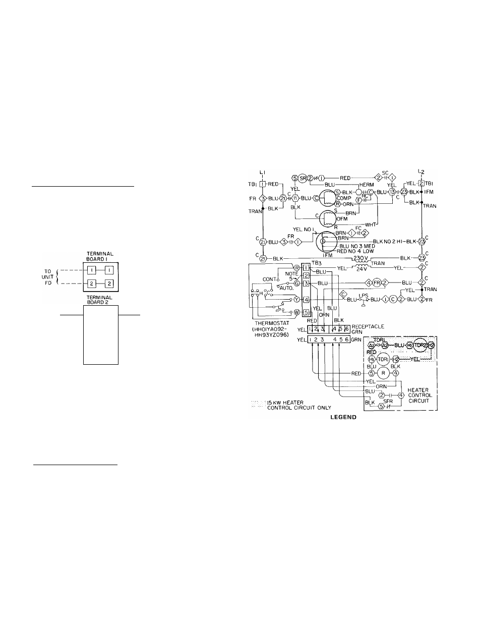
Fig. 7 — Line Power Connections Evaporator Fan Motor is factory wired for high THERMOSTAT LEADS (24 v) are brought thru hole provided (Eig. 1) into low voltage section of control box. Connect leads to Terminal Board 3 as Accessory Electric Heaters — Extend control leads &- № &- -a -Q 0------------------------------------ a Connect Terminal G to Terminal 2 for operation with electric _____ Field Wiring *HH01 YA092 thermostat with HH93YZ096 subbase Fig. 8 — Thermostat Connections c — Contactor TC — Thermostat, Cooling Comp — Compressor TDR — Time-Delay Relay FC — Fan Capacitor (1FM) TH — Thermostat, Heating FR — Fan Relay Tran — Transformer IFM — Indoor Fan Motor LPS — Low-Press. Switch — Field Power Wiring OFM — Outdoor Fan Motor ___ . Field Control Wiring R — Relay NEC Class 2, 24 v. RC — Run Capacitor (Dual) o SC — Start Capacitor Marked Connections SFR — Safety Fan Relay O Unmarked Connections SR — Start Relay TB — Terminal Board □ Terminal Board Connections NOTES 1. To be wired in accordance with NEC and local codes 2 Low-pressure cutout setting 27 0 ± 4 psig. 3. Terminations in junction box suitable for NEC Class 2 control circuit, at 24 volts 4 Motor provided with inherent thermal protector, 5. Terminal G connects to terminal no 2 for operation with electric heater.Terminal G connects to terminal no. 3 for operation with out electric heater Fig. 9 — Typical System Wiring Diagram
speed operation as shown in Fig. 9. If medium or
low speed operation is desired, remove black motor
lead from Contactor Terminal 23 and replace with
blue motor lead for medium speed or red motor
lead for low speed. Tape unused leads separately.
shown in Eig. 8 and 9.
with plug (supplied with heater) thru fan section
and insert plug into receptacle located on side
panel of control box. See Fig. 6 and 9.
heater or Terminal 3 for operation without electric heater