Fig. 2 — roll filter section, rfs1 shown, Roll filter section description – Carrier 39E User Manual
Page 2
Attention! The text in this document has been recognized automatically. To view the original document, you can use the "Original mode".
PRESSURE SWITCH
ADJUSTING SCREW
(UNDER RED CAP)
PRESSURE SWITCH
HIGH-PRESSURE
PORT
POWER SWITCH
(ON-OFF)
MANUAL OVERRIDE
SWITCH
(AUTO-MANUAL)
CONTROL BOX
LOWER ACCESS
PANEL
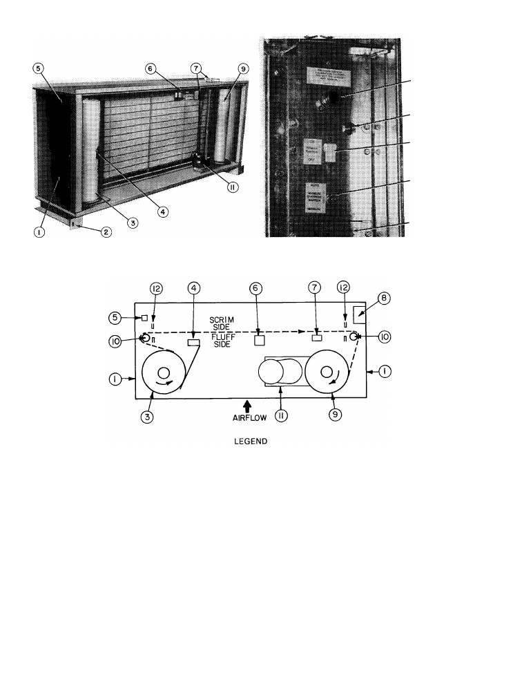
CONTROL BOX (ITEM 81 DETAILS
1 — Access Door (both sides)
2 — Suspension Bracket
3 — Supply Spool Assembly
4 — Media Runout Switch
5 — Media Switch
6 — Pulse Generator Switch
7 — Junction Box (position varies; see text)
8 — Control Box
9 — Take-Up Spool Assembly
10 — Idler Shaft (both sides)
11 — Motor Gear Drive Assembly
12 — Seal (both sides)
----------- Media Path
Fig. 2 — Roll Filter Section, RFS1 Shown
ROLL FILTER SECTION DESCRIPTION
(Fig, 2 and 3)........ AU sections have side access
doors hasisg safety latches, A 1 4~in. x 20 lx)ií
prevents door latch from opening unless bolt is
removed. (Do not operate air system when an>
access door is open. Be sure to replace safety bolt
after dootx are closed.) Left-hand door provides
access to roll media supply spool and a media
switch. Right-hand side of section, in addition to
take-up spool and its motorized gear drive, con
tains also a control panel, a field wiring jtmetion
box, and where applicable, an mdicator light box
for remote mounting.
The 65-ft of roll media advance from left to
right as shown. ,Medta Is monitored by a runout
switch and a metering device for full span media
travel. Replacement rolls of filter media (65-ftl
may be shipped with section for future use,
i,argest model (39E-90) consists of 2 roll media
assembUes in a common enclosure, lipper assem
bly (slave) Is coupled to lower assembly for
tandem operation by a common control drive
arrangement.