Carrier 39E User Manual
Page 11
Attention! The text in this document has been recognized automatically. To view the original document, you can use the "Original mode".
1. Loosen adjusting screw locknut.
2. Turn adjustable bolt so that runout switch opens
when runout arm comes within 3/8-in. of core.
3. Tighten adjusting screw locknut. Recheck
setting.
Pressure Switch
(Fig. 2) — As filter media be
comes dirty, high-pressure drop thru media reduces
airflow. Pressure switch is factory set at 0.55 in. wg.
Field adjustment should not be necessary. When
pressure sensed by high-pressure fitting on control
panel face reaches this setting, pressure switch shuts
off amber operating light and energizes pulse gener
ator sequence relay and motor. As clean media ad
vances across airway, pressure drop across media
decreases and switch returns to illuminate amber
operating light. To check and/or adjust pressure
switch setting:
1. Shut off system air fan. Open take-up side
access door. Shut off power at fused disconnect.
Set power switch at OFF.
2. Disconnect yellow or gray motor lead at ter
minal board no. 1 (TBl-3 or 4) to prevent motor
operation. Tape off lead.
3. Set power switch at ON. Turn on power at
fused disconnect.
4. Remove red plastic cap from pressure switch to
expose adjusting screw. Do not loosen 1-in. hex
locknut. Nut is locked to provide mechanical
stop for minimum differential pressure setting.
5. Connect a draft gage to high-pressure port on
control panel.
6. Apply controlled pressure gradually to high-
pressure port until amber operating light goes
out. Note draft gage reading. This is switch set
point (factory setting 0.55 in. wg).
7. Turn adjusting screw counterclockwise to de
crease static pressure setting or clockwise to
increase static pressure setting as required. A
1/2 turn changes setting approximately 0.13
in. wg.
8. Remove draft gage. Replace red plastic cap on
adjusting screw.
9. Shut off power at fused disconnect. Set power
switch at OFF. Reconnect motor lead. Turn on
power at fused disconnect. Set power switch
at ON.
10. Perform any other operational checks as re
quired. Close and secure access door. Restore
air system operation.
Motor Gear-Drive Assembly
(Fig. 2 and 10) —
Assembly advances clean media across filter section
airway. It consists of a motor and drive sprocket,
a roller chain and a take-up spool sprocket on a
support plate. Chain tension is factory set so that
deflection of chain at midpoint is 1/4-inch. To ad
just chain tension, loosen motor mounting bolts (3),
reposition motor on slotted mounting holes in
support plate until correct tension is achieved.
Tighten motor hold-down bolts.
MOTOR
TAKE-UP
SPOOL
SPROCKET
SUPPORT PLATE
MOUNTING HOLES (4)
MOTOR MOUNTING
BOLTS. LOOSEN FOR
TENSION ADJUSTMENT
Fig. 10 — Motor Gear-Drive Details
Lubricate chain with a light graphite oil once each
year.
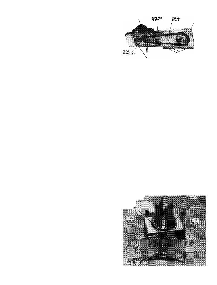
Media Tension Brake
(Fig. 11) — Brake is
mounted on bottom panel of supply spool side to
provide tension on supply spool at bottom end of
spool shaft. Two brake shoes held in place by 2
helical springs cause friction (drag) required for
proper media tension. Brake assembly includes
supply spool bearing surface and slotted axis shaft.
Except for making sure that helical springs and shoes
are in tension, no other maintenance is required.
Shear Pin
— Take-up spool shaft is fastened to
keeper on take-up spool disk at base of spool by a
bolt and locknut. This bolt acts as a shear pin to pre
vent damage to motor gear-drive. In the event of
mechanical failure which could cause excessive
tension on motor gear-drive, bolt will shear allowing
motor to operate freely and continuously. Eventu
ally, amber operating light will go out (as described
elsewhere) and stay out as indication of malfunction.
Cleaning and Lubrication
— The only cleaning
necessary in addition to general housekeeping is
removal of loose fibers around shaft bearings. Shaft
bearings and gear motor require no routine main
tenance. Refer to specific component description for
additional information as required.
BRAKE
SKIES:
Fig. 11 — Media Tension Brake
11