Service – Carrier 39E User Manual
Page 10
Attention! The text in this document has been recognized automatically. To view the original document, you can use the "Original mode".
SERVICE
Replacing Dirty Filter Media
— Rethreading
clean media roll is not necessary. When clean media
is to be installed, simply attach leader of clean media
roll to trailer of depleted (dirty) media roll as
follows;
1. Shut off system air fan. Open both side access
doors (Fig. 2). Automatic units — set manual
override switch at MANUAL.
2. Check that supply media roll has been depleted.
Swing media runout arm away from supply
spool and set media switch at ON so that motor
will advance remaining media. When paper
trailer is exposed, release runout arm (stopping
motor). Then set media switch at OFF.
NOTE: If a complete increment of clean media
can be exposed to airway before paper trailer on
supply spool is exposed, adjust media runout
switch as described later so that clean media will
not be wasted.
3. Disengage paper trailer from supply core (card
board tube). Do not operate motor at this time.
4. Lift supply spool upper shaft retainer, swing
out upper end of shaft. Remove the now empty
core from supply spool. Do not damage or dis
card core.
5. Unpack replacement supply media roll, install
it on supply spool. Replace upper end of spool
in retainer. Note correct position of roll so that
as media unrolls fluff side of media will be facing
into airstream (Fig. 2).
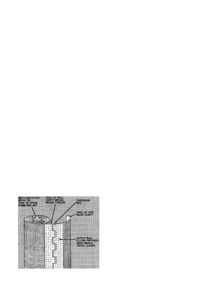
6. Connect paper leader of replacement media roll
to paper trailer of depleted media roll by using
threading rod (Fig. 9).
7. Dual-roll sections only — Jog media switch to
expose paper trailer of upper (slave) media roll.
As this is done, be sure that threading rod in
Fig. 9 — Replacement Media Roll Spliced
to Depleted Media Roll
splice in lower media rolls passes smoothly
around supply-side idler shaft and then thru
supply-side seals without snagging or wrinkling.
Repeat steps 2 thru 6 to replace upper media
roll.
8. Set media switch at ON to draw splice(s) across
airway opening. Check that threading rod(s),
splice(s) and media travel smoothly. When
(lower) threading rod and splice reach take-up
side set media switch at OFF.
9. Remove threading rod to disconnect paper
trailer of depleted roll from paper leader of
replacement roll. Replace threading rod on its
storage clips in supply side.
10. Lift take-up spool shaft retainer; swing out
upper end of take-up spool. Remove depleted
media roll from take-up spool. Pack dirty media
roll in now-empty replacement roll carton. Dis
pose of dirty media roll as suitable.
11. Install empty core (cardboard tube removed in
step 4) on take-up spool. Replace upper end of
take-up spool shaft in shaft retainer.
12. Insert leader behind strap on take-up core
(Fig. 8). Fold leader over itself. Note rotation
of take-up spool (Fig. 2).
13. Set power switch at OFF.
14. Set media switch at ON.
15. Jog power switch so that about 2 turns of clean
media roll winds up on take-up spool to secure
paper leader end of roll on to core. On dual-roll
sections this will also advance upper media roll
so that splice will pass thru upper take-up-side
seals, pass around take-up idler shaft and reach
upper take-up spool.
16. Dual roll sections — Disconnect splice in upper
depleted and replacement rolls; connect upper
replacement media roll to upper take-up spool
(i.e. repeat steps 9 thru 15). Be sure that media
travels smoothly and that paper leader is evenly
secured. Replace threading rod in its storage
clips on supply side.
17. Manual Units — Leave media switch at ON. Set
power switch at OFF.
Automatic Units — Set manual override switch
at AUTO. Set media switch at ON, then set
power switch at ON.
18. To check that all is in order, perform Opera
tional Checks as required. Close and secure
access doors before leaving job site.
Media Runout Switch
(Fig. 2) — Switch is factory
set to prevent media advancement when supply
spool media is depleted. Incorrect setting may
cause excessive media to remain on supply spool
or cause media to be pulled off supply spool core
before shutting off advance cycle.
Runout switch is activated by adjustable bolt on
runout arm when arm is 3/8-in. away from spool
core. To adjust cutout setting:
r
10