38af air-cooled condensing units, Table 3 — liquid line data, Fig. 2 — line power connections – Carrier 38AF User Manual
Page 3
Attention! The text in this document has been recognized automatically. To view the original document, you can use the "Original mode".
HEATING A COOLING
38AF
Air-Cooled Condensing Units
Table 3 — Liquid Line Data
UNIT 38AF
MAX
ALLOWABLE
LIQUID
LIFT (it)
LIQUID LINE
Max Allowable
Pressure Drop
(psi)
Max Allowable
Temp Loss
(F)
007
70
7
2
008
70
7
2
NOTE: Values shown are for units operating at 45 F saturated suction
and 95 F entering air
3-PHASE
CONN TO
DISCONNECT
PER N E C
___________________________
. SPLICE CONNECTIONS
FIELD WIRING
FACTORY WIRING
YEL-
BLK-
-BLU -
-GROUND LEAD------ GROUNDING LUG
3-PHASE COND UNIT
NOTE: Pigtail connections can use copper or aluminum wire Factory-
supplied connectors must be used when aluminum wire is used
Fig. 2 — Line Power Connections
JUMPER
TERMINAL
BLOCK
UNIT
CONTROL
BOX
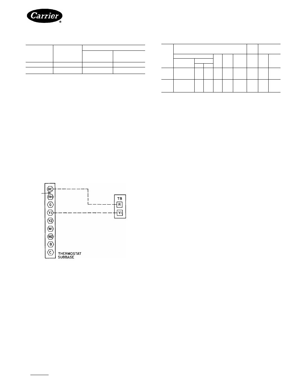
Fig. 3 — Remote Thermostat Wiring
START-UP
Preliminary Checks
1. Check that all internal wiring connections are tight
and that all barriers, covers and panels are in place.
2. Field electrical power source must agree with unit
nameplate rating.
3. All service valves must be open.
4. Crankcase heaters must be firmly seated into com
pressor crankcase.
Leak Test entire refrigerant system by pressure method
described in Carrier Standard Service Techniques
Manual, Chapter 1, Section 1-6. Use R-22 at approxi
mately 25 psig backed up with an inert gas to a total
pressure not to exceed 245 psig.
Table 4 — Electrical Data (3-Ph/60-Hz)
38AF
UNIT
FAN
COM
PRESSOR
Volts
ICF
MCA
MOCP
(Fuse)
FLAT
RLA
LRA
Nameplate
Supplied*
Min
Max
208-230
187
253
140
36 3
60
29
26 7
137
007
460
414
528
71
166
25
1 5
12 1
69
575
518
666
58
14.9
20
2.9t
9.6
55
208-230
187
253
186
44 4
60
29
32 5
183
008
460
414
528
93
20 9
25
1 5
152
91
575
518
666
76
188
25
2 9Í
124
73
FLA
— Full Load Amps
ICF
— Maximum Instantaneous
Current Flow
LRA
— Locked Rotor Amps
MCA
— Minimum Circuit Amps per NEC Section 430-24
MOCP
— Maximum Overcurrent Protection
RLA
— Rated Load Amps (compressor)
•Units are suitable for use on electrical systems where voltage supplied
to the unit terminals is not below or above the listed limits
tFan motor is single phase
j230 volts
Before starting unit, crankcase heaters must be on for '
24 hours to be sure all refrigerant is out of the oil. To
energize crankcase heaters, proceed as follows; set space
thermostat above ambient so there will be no demand for
cooling. Close field disconnect. The crankcase heaters '
are now energized.
Evacuate and Dehydrate entire refrigerant system
by either of the methods described in Carrier Standard
Service Techniques Manual, Chapter 1, Section 1-7.
Charge System — Refer to Carrier Standard
Service Techniques Manual, Chapter 1, Section 1-8.
Using liquid charging method and charging by weight
procedure, charge to a clear sight glass. After proper
charge has been determined, indicate this amount on
unit’s aluminum informative plate section entitled
“Refrig./System R-22.”
To Start Unit — Assuring that crankcase heater has
been on for 24 hours and field disconnect is closed, set
room thermostat below ambient. Unit compressor will
start after a 15-second delay.
SERVICE
Crankcase Heater prevents refrigerant migration and
compressor oil dilution during shutdown when com
pressor is not operating. If crankcase heater is da-
energized for more than 6 hours, both compressor service
valves must be closed.
Condenser Fan is supported by a reinforced wire
guard to which the fan motor is bolted.
Figure 4 shows proper mounted fan position.
Lubrication
FAN MOTORS have permanently sealed, lubricated
bearings. Do not oil.
COMPRESSOR also has its own oil supply.
CONDENSER FAN ADJUSTMENT (Fig. 4) — Shut
off unit main power supply. Remove condenser fan
assembly (grille, motor, motor cover and fan) and loosen
fan hub setscrews. Adjust fan height as shown in Fig. 4.
Tighten setscrews and replace fan assembly.
Cleaning Coils ^ Coils can be cleaned with a vacuum
cleaner, washed out with water, blown out with com
pressed air, or brushed (do not use wire brush). Fan
motors are drip proof but not waterproof.
Manufacturer reserves the right to discontinue, or change at any time, specifications or designs without notice and without incurring obligations.
Book 11 14
PC111
Catalog No 563-852
PrintedinUSA
Form38AF-1SI
Pg3
4-85
Replaces: New
For replacement items use Carrier Specified Parts.
Tab I3al2a