38af air-cooled condensing units – Carrier 38AF User Manual
Page 2
Attention! The text in this document has been recognized automatically. To view the original document, you can use the "Original mode".
HEATING & COOLING
38AF
Air-Cooled Condensing Units
Step 3 — Complete Refrigerant Piping
Connections
SIZE REFRIGERANT LINES — Consider length of
piping required between condensing unit and evaporator,
amount of liquid lift, and compressor oil return. See
Table 3 and also refer to Part 3 of Carrier System Design
Manual for design details and line sizing. Refer to evap
orator installation instructions for additional information.
USE FILTER DRIER AND MOISTURE INDICATOR
— The filter drier is factory supplied. Moisture indicator
(sight glass) is a field-installed option and should be
installed just after liquid line shutoff valve. Do not use a
receiver; there is none provided with unit and one should
not be used.
MAKE PIPING CONNECTIONS — Remove block-off
in corner post and unsweat caps from liquid and suction
lines.
NOTE: Unit is shipped with R-22 holding charge. System
pre.ssure must be relieved before unsweating caps.
Pass nitrogen or other inert gas through piping while
brazing to prevent formation of copper oxide.
Install field-supplied thermostatic expansion valve(s)
to evaporator section. If 2 thermostatic expansion valves
are installed for 2-step cooling, install field-supplied
liquid line solenoid valve ahead of the second expansion
valve.
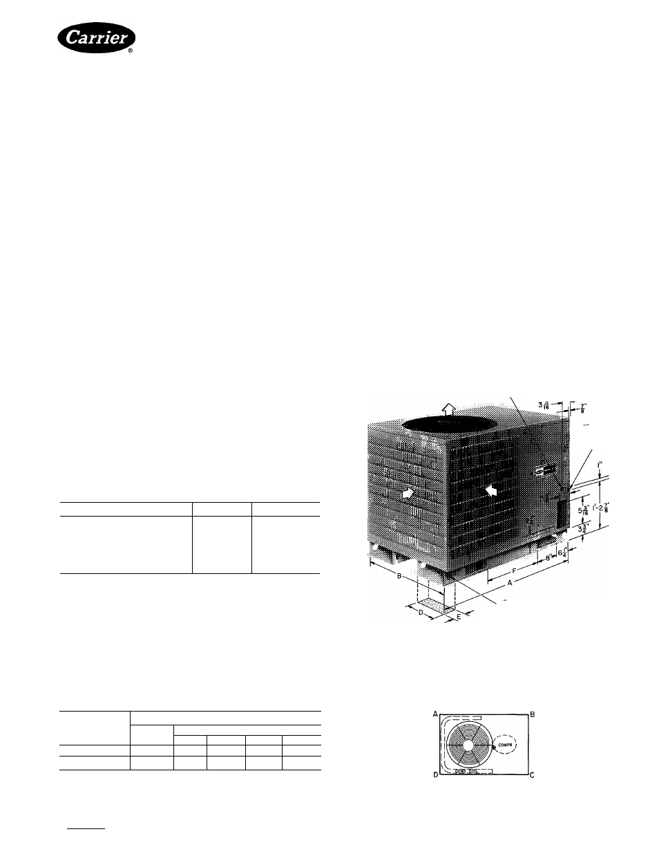
DIMENSIONS (ft-in.)
UNIT 38AF
007
008
Length
A
2-9
4- 0%
Width
B
2-9
2- 8Va
Height
c
2-8
2-11
'/s
Base Rail Width
D
0-10'/2
O-IO'/j
Minimum Support
E
0-4
0- 4
Lift opening
separation
F
1- 0’/4
1-10
NOTE Units may be installed with any one side, except compressor access
side, within one ft of wall or other airflow obstruction as long as remaining
sides have at least 3 ft clearance Compressor side access is always 3 feet
Units may be located side by side with a minimum of 3ft between units
Allow at least a 5-ft clearance above the unit
PROVIDE SAFETY RELIEF —A fusible plug is located
in unit liquid line. Do not cap this plug. If local code;
requires additional safety devices, install as directed.
Step 4 — Complete Electrical Connections
POWER WIRING — Unit is factory wired for voltage
shown on nameplate. Provide adequate fused disconnect
switch within sight of unit, readily accessible, but out of
reach of children. Provision for locking switch open (ofO
is advisable to prevent power from being turned on while
unit is being serviced. Disconnect switch, fuses, and field
wiring must comply with National Electrical Code and
local code requirements.
Route power wires through opening in unit side panel
and connect in unit control box as shown on unit label
diagram and Fig. 2. Unit must be grounded.
Affix crankcase heater warning sticker to unit dis
connect switch.
CONTROL CIRCUIT WIRING — Control voltage is
24 volts. See Fig. 3 and unit label diagram for field-
supplied wiring details. Route control wires through
opening in unit side panel to connection in unit con
trol box.
if" HOLE FIELD POWER SUPPLY
i HOLE
CONTROL
POWER
l-b
rigging
HOLE (8)
Fig. 1 — Dimensions (ft-in.)
Table 2 — Weight Distribution
WEIGHT (lb)
UNIT 38AF
Oper
Support Point
Wt
A
B
C
D
007
300
54
78
100
68
008
410
75
116
133
86
REAR
LEFT
RIGHT
FRONT
TOP VIEW
Manufacturer reserves the right to discontinue, or change at any time, specifications or designs without notice and without incurring obligations.
Book 11 14
PC111
Catalog No 563-852
PrintedInUSA
Form38AF-1SI
Pg2
4-85
Replaces: New
For replacement items use Carrier Specified Parts
Tab |3al2a