Single-stage heat s cool- autochangeover, Frrw, N-rvri – Carrier 48KHA User Manual
Page 8: Fig. 8—high- and low-voitage connections, Table 3—electrical data (60 hz)
Attention! The text in this document has been recognized automatically. To view the original document, you can use the "Original mode".
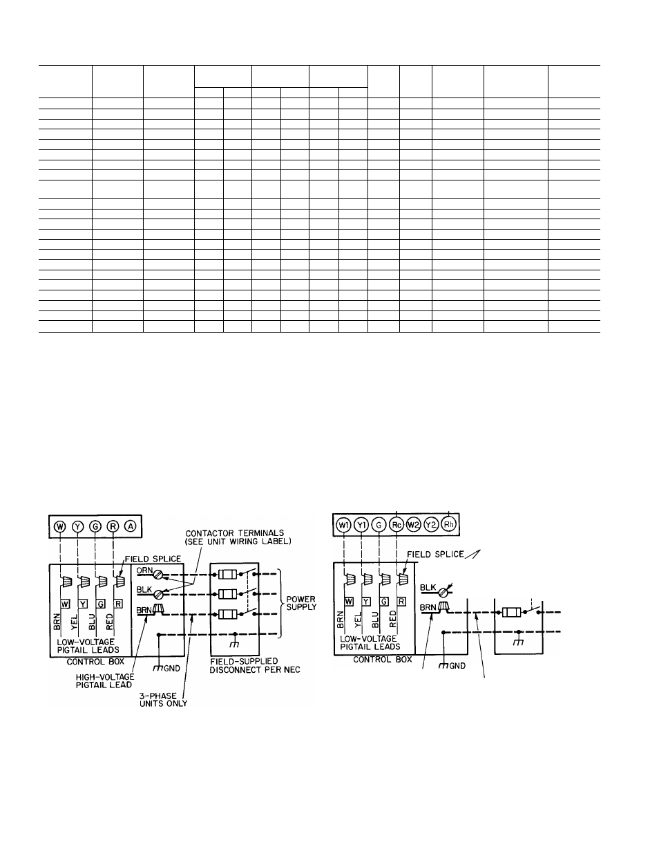
Table 3—Electrical Data (60 Hz)
MODEL
48-
SERIES
VOLTS-
PHASE
OPERATING
VOLTAGE*
COMPR
FLA
MCAt
MAX
AMPS
MAX FUSE
SIZE
(Amps)t
MIN WIRE
SIZE (AWG)t
(75C Copper)
MAX
WIRE
LENGTHt
Min
Max
RLA
LRA
IFM
OFM
KLA118
310BE
208/230-1
197
253
8.7
49.0
1.2
1.0
13.1
10.9
20
14
76
KLA124
310BE
208/230-1
197
253
11.7
63.0
1.7
1.0
17.4
14.4
25
12
89
KHA024
310BF
208/230-1
197
253
11.7
63.0
3.0
1.0
18.7
15.7
25
12
82
KLA130
310BE
208/230-1
197
253
13.7
76.0
3.1
1.0
21.2
17.8
30
10
115
KHA030
310BF
208/230-1
197
253
13.7
76.0
2.9
1.0
21.0
17.6
30
10
116
KLA136
310BE
208/230-1
197
253
17.6
88.0
4.6
1.0
27.6
23.2
40
10
88
KLA136
510CE
208/230-3
187
253
11.5
65.1
4.7
1.0
20.1
17.2
25
10
137
KLA136
610CE
460-3
414
506
5.1
32.8
1.9
0.6
8.9
7.6
15
14
272
KHA136
KHA036
310BE
310BF
208/230-1
197
253
17.6
88.0
3.8
0.8
26.6
22 2
40
10
92
KHA136
510CE,CF
208/230-3
187
253
11.5
65.1
5.6
1.0
21.0
18.1
25
10
130
KHA036
510CF
208/230-3
187
253
11.5
65.1
5.6
1.0
21.0
18.1
25
10
130
KLA142
310BE
208/230-1
197
253
23.9
95.4
4.1
0.8
34.8
28.8
50
8
113
KLA142
510CE
208/230-3
187
253
15.3
82.0
5.6
1.0
25.8
21.9
35
10
108
KHA042
310BF
208/230-1
197
253
23.9
95.4
3.9
0.8
34.6
28.6
50
8
114
KHA042
510CF
208/230-3
187
253
15.3
82.0
5.0
1.0
25.2
21.3
35
10
111
KLA148
310BE
208/230-1
197
253
23.7
116.0
4.5
1.9
36.1
30.1
50
8
108
KLA148
510CE
208/230-3
187
253
14.7
92.0
7.8
2.2
28.4
24.7
35
10
96
KLA148
610CE
460-3
414
506
7.0
46.0
3.3
1.2
13.3
11.5
20
14
180
KHA048
310BF
208/230-1
197
253
23.7
116.0
3.7
1.9
35.3
29.3
50
8
111
KHA048
510CF
208/230-3
187
253
14.7
92.0
5.8
2.2
26.4
22.7
35
10
104
KLA160
310BE
230-1
207
253
27.8
130.0
6.2
1.9
42.9
35.9
60
8
100
KHA060
310BF
230-1
207
253
27.8
130.0
6.5
1.9
43.2
36.2
60
8
99
AWG—
American Wire Gage
FLA
—Full Load Amps
IFM
—Indoor Fan Motor
LRA
—Locked Rotor Amps
MCA—
Maximum Circuit Ampacity
OFM
—Outdoor Fan Motor
RLA
—Rated Load Amps
*Voltage limits between which the unit will operate satisfactorily
tif other than 75 C copper wire is used, determine size from unit ampacity and the National Elec
trical code. Voltage drop of wire must be less than 2% of unit rated voltage Maximum wire
length is for one way along the wire path from unit to service panel
:(;Maximum dual element size
SINGLE-STAGE HEAT S COOL-
MANUAL CHANGEOVER
SINGLE-STAGE HEAT S COOL-
AUTOCHANGEOVER
JUMPER-H------------------- 1
CONTACTOR
TERMINALS
(SEE UNIT WIRING LABEL)
—♦frrw^--- '
------->n-rvri —
HIGH-VOLTAGE
PIGTAIL LEAD
FIELD-SUPPLIED
DISCONNECT PER NEC
3-PHASE
UNITS ONLY
. Field Low-Voltage Wiring
.Field High-Voltage Wiring
. Factory Low-Voltage Wiring
, Factory High-Voltage Wiring
NOTE:
For
manual
changeover
applications,
use
thermostat
part
no.
HH01AD042
with
subbase part no HH93AZ042, or thermostat part no HH01AD040 with subbase part no
HH93AZ040
For automatic changeover, use thermostat part no. HH07AT174 with subbase part no.
HH93AZ096; or thermostat part no HH10AD041 with subbase part no HH93AZ041.
Fig. 8—High- and Low-Voitage Connections