Important- read before installing, Installation step 1—rig and place unit, A caution – Carrier 48KHA User Manual
Page 2
Attention! The text in this document has been recognized automatically. To view the original document, you can use the "Original mode".
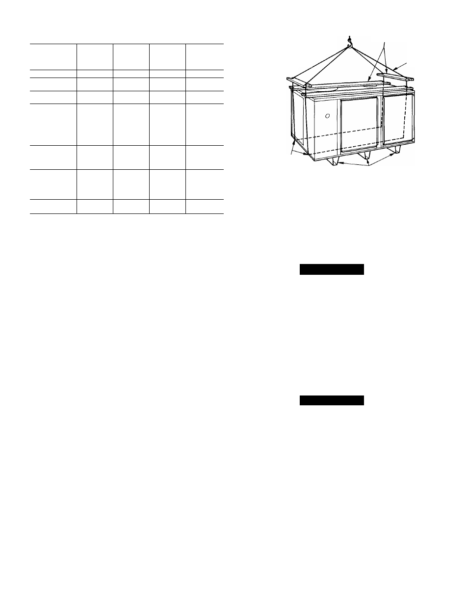
Table 1—Performance Data
MODEL 48-
COOLING
CAPACITY
(Btuh)*
RATED
HEATING
INPUT
(Btuh)
OUTPUT
CAPACITY
(Btuh)
ARI*
SOUND
RATING
(Bels)
KLA118310BE
17,800
40,000
32,000
7.8
KLA124310BE
23,800
40,000
32,000
7.8
KHA024310BF
24,000
75,000
58,000
8.0
KLA130310BE
29,600
40,000
32,000
7.8
KHA030310BF
29,600
75,000
58,000
7.8
KLA136310BE
36,000
60,000
47,000
8.0
KLA136510CE
36,000
60,000
45,000
8.0
KLA136610CE
36,000
60,000
45,000
8.0
KHA136310BE
36,000
100,000
79,000
8.0
KHA136S10CE
36,000
100,000
75,000
8.0
KHA036310BF
36,000
125,000
97,000
8.0
KHA036510CF
36,000
125,000
93,750
8.0
KLA142310BE
42,000
60,000
47,000
78
KLA142510CE
42,000
60,000
45,000
7.8
KHA042310BF
42,000
125,000
97,000
7.8
KHA042510CF
42,000
125,000
93,750
7.8
KLA148310BE
49,000
80,000
63,000
8.4*
KLA148510CE
49,000
80,000
60,000
8.4*
KLA148610CE
49,000
80,000
60,000
8.4*
KHA048310BE
49,000
125,000
97,000
8.4*
KHA048510CF
49,000
125,000
93,750
8.4*
KLA160310BE
60,000
100,000*
79,000*
8.4*
KHA060310BF
60,000
150,000*
116,000*
8.4*
♦Rated in accordance with U S. Government D.O.E. test procedures and/
or ARI Standard 210-81.
tSound rating per ARi 270-84.
tThe capacity ratings of singie-phase units are in accordance with U.S.
Government D.O.E. test procedures and/or AGA certification require
ments. For 3-phase units, the efficiency rating is a product thermai effi
ciency rating determined under continuous operating conditions, inde
pendent of any installed system.
All units can be connected into existing duct systems that
are properly sized and designed to handle an airflow of 350
to 450 cfm per each 12,000 Btuh of rated cooling capacity.
See Table 8 for cooling euid heating airflow requirements.
NOTE:
When insteJling any accessory item, see Installation
Instructions packaged with accessory.
IMPORTANT-
READ BEFORE INSTALLING
1. This instEdlation must conform with all applicable
local and nationed codes.
2. Power supply (volts, hertz and phase) must corre
spond to that specified on unit rating plate.
3. Electrical supply provided by utility must be suffi
cient to handle load imposed by unit.
4. Refer to Fig. 4 for locations of gas inlet, electrical
inlets, condensate drain, duct connections, and
required clearances before setting unit in place.
5. Locate unit where vent cap will be a minimum of 4 ft
from openable windows or doors.
6. Installation must conform with local building codes
and with National Fuel Gas Code, NFPA 54-1984/
ANSI Z223.1-1984.
IMPORTANT: On some models, the high-voltage igni
tion cable is not connected to the spark generator termi
nal on the control head/gas valve assembly when shipped
from the factory. The cable is fastened to the manifold on
these models. Push the boot toward center of the cable to
expose the connector on the end of the cable. Attach the
connector securely to the terminal on the end of the con
trol head/gas vedve assembly. Push the boot over connec
tor to insulate the high-voltage connection.
SPREADER OARS'
^
(2)2x4xUNIT LENGTH PLUS 10"WITH
11 DEEP 90° NOTCHES EACH END
(2) 2x4xUNIT WIDTH WITH l^
DEEP 90° NOTCHES
EACH END
SPREADER BARS
LOCATE CHAINS THROUGH
HOLES IN BASE
CHANNELS
CHAIN
TWO OR THREE BASE
CHANNELS ATTACHED TO
BOTTOM OF UNIT
Fig. 2—48KHA,KLA Suggested Rigging
INSTALLATiON
Step 1—Rig and Place Unit
A CAUTION
When rigging unit to be hfted, use spreader bars to pro
tect top and sides. Rig unit as shown in Fig. 2. Use
extreme caution to prevent damage when moving unit.
Unit must remain in upright position during all rigging
and moving operations. Unit must be level for proper
condensate drainage; therefore, the ground-level pad or
accessory roof-mounting curb must be level before set
ting unit in place. When a field-fabricated support is
used, ensure that support is level and properly supports
unit and plenum.
ROOFTOP INSTALLATION
A CAUTION
When installing a unit on a rooftop, be sure roof will
support the additioneil weight. Refer to Fig. 4 to obtain
total weight and corner weight information.
When installing a Model 48KHA,KLA end discharge unit
with a field-supplied downflow plenum, a field-supplied roof
mounting curb must be installed on emd flashed into roof
before
unit
installation.
When
installing
a
Model
48KHA,KLA end discharge unit without a downflow ple
num, place unit on a level base that provides proper sup
port. On flat roofs be sure unit is located at least 4 in. above
highest expected water level on roof to prevent flooding.
Consult local codes for additional installation requirements.
GROUND LEVEL INSTALLATION-Place unit on a
solid, level concrete pad that is a minimum of 4 in. thick and
that extends approximately 2 in. beyond casing on all sides
of unit. Do not secure unit to pad except when required by
local codes.
CLEARANCES—Required minimum operating and service
clearances are shown in Fig. 4 for providing adequate com
bustion, ventilation emd condenser edr.