A caution, Service – Carrier 48KHA User Manual
Page 16
Attention! The text in this document has been recognized automatically. To view the original document, you can use the "Original mode".
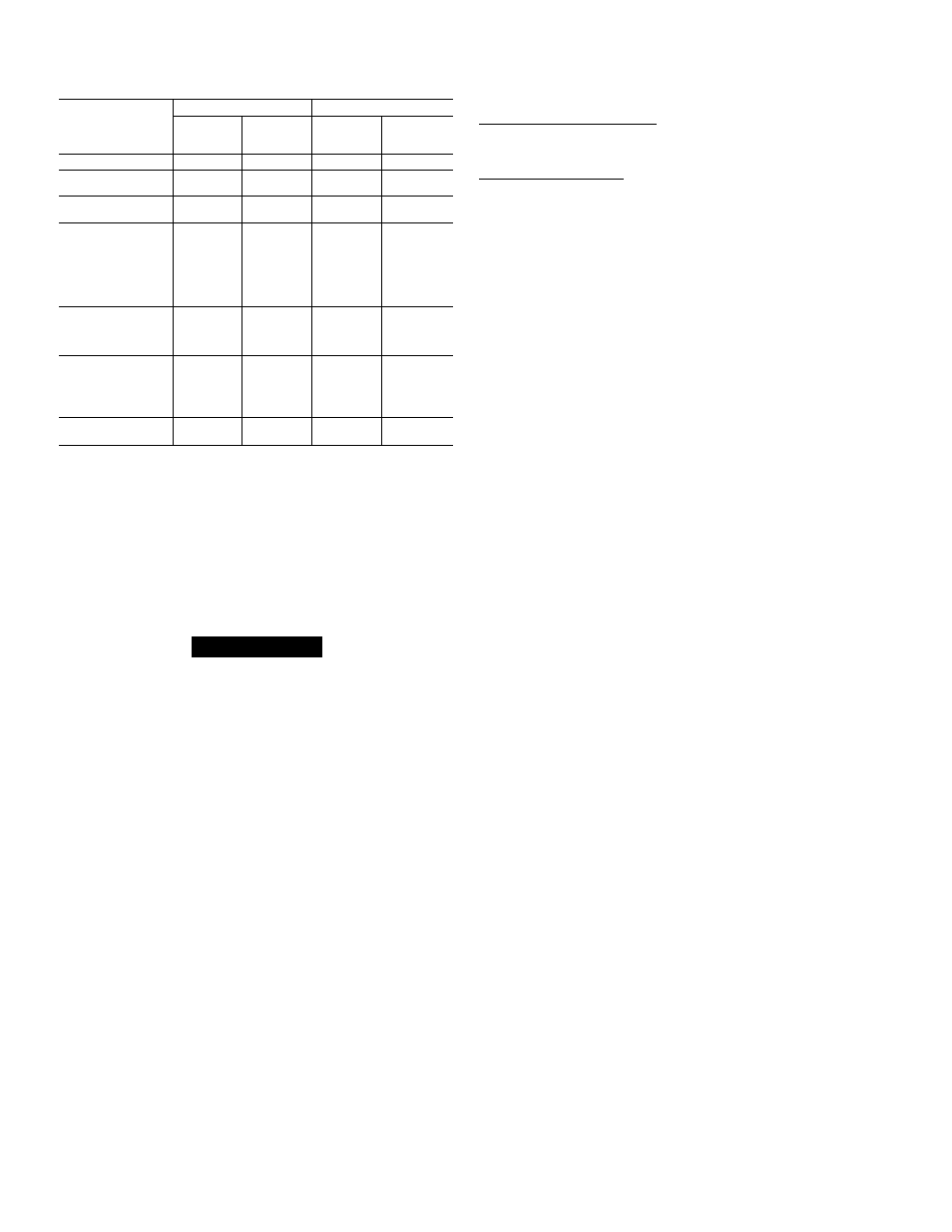
Table 8—Rated Cooling and Heating Airfiows
MODEL 48-
COOLING
HEATING
Rated
Airflow
(dm)*
ESP
(in. wg)
Rated
Airflow
(cfm)*
Maximum
ESP
(in. wg)*
KLA118310BE
630
0.10
505
0.30
KLA12431 QBE
800
0.10
505
0.30
KHA024310BF
800
0.10
947
0.30
KLA13031 QBE
1000
015
462
0.30
KHA030310BF
1000
0.15
947
0.30
KLA136310BE
1200
0.15
758
0.30
KLA136510CE
1200
0.15
758
0.65
KLA136610CE
1200
0.15
758
0.65
KHA136310BE
1200
0.15
1155
0.30
KHA136510CE
1200
015
1155
0.65
KHA036310BF
1200
0.15
1445
0.30
KHA036510CF
1200
0.15
1445
0.65
KLA142310BE
1400
015
695
0.30
KLA142510CE
1400
0.15
695
0.65
KHA042310BF
1400
0.15
1445
0.30
KHA042510CF
1400
0.15
1445
0.65
KLA148310BE
1600
0 20
925
0.30
KLA148510CE
1600
0.20
925
0.65
KLA148610CE
1600
0.20
925
0.65
KHA048310BF
1600
0.20
1445
0 30
KHA048510CF
1600
0.20
1445
0.65
KLA160310BE
2000
0.20
1155
0.30
KHA060310BF
2000
0.20
1735
0.30
ESP
—External Static Pressure
♦Rated in accordance with U.S Government D.O.E. test procedures and/
or ARI Standard 210-81
NOTE:
When operating the 208/230-volt, 3-phase versions
of Model 48KHA048 at 208 volts, lead connections of
blower motor must be changed as indicated on unit wiring
label to ensure proper airflow.
A CAUTION
Do not change blower-motor lead connections on 460-v
units from factory setting.
Heating and/or cooling airflow of 208/230-v direct-drive
blower motors can be changed by changing the lead con
nections of blower motor. Motor leads are color-coded as
follows:
black—high, speed
blue —medium speed
red —low speed
NOTE:
Some direct-drive blower motors do not bave lead
for medium speed. Factory connections and available
optional connections are shown in Table 6.
For all units, motor lead connected to heat relay determines
heating speed and resulting airflow; and motor lead con
nected to cooling relay determines the cooling speed and
resulting airflow. See unit wiring label.
To change heating and/or cooling speed, connect appropri
ate color-coded lead to appropriate relay. Be sure to prop
erly insulate any unused motor lead. See Make Wiring
Connections, Special Procedures for 208-v Operation section
for proper procedures to insulate an unused electrical lead.
When installing a 208- or 230-v direct-drive unit that is
factory-connected for heating and cooling speeds that are
not the same, and seune speed for both heating and cooling
is required for a particular application, connect appropriate
color-coded lead to terminal 2 of cooling relay and connect a
field-supplied jumper between heat relay and terminal 2 of
cooling relay. Be sure to properly insulate unused motor
lead(s).
CONTROLS—All compressors have the following interned-
protection controls:
High-Pressure Relief Valve—This vedve opens when pres
sure differential between low and high side becomes
excessive.
Compressor Overload—This overload interrupts power to
compressor when either current or internal temperature
becomes excessive, and automaticedly resets when internal
temperature drops to a safe level. This overload may require
up to 60 minutes (or longer) to reset; therefore, if internal
overload is suspected of being open, disconnect electrical
power to unit and check circuit through overload with an
ohmmeter or continuity tester.
COOLING SEQUENCE OF OPERATION-The following
sequence of operation pertains to all 208/230-volt, 3-phase
units; however, sequence of operation of single-phase and
460-volt units is very similar. Refer to wiring diagram in
Fig. 10.
NOTE:
Although actued unit wiring may vary slightly from
that shown in Fig. 10, sequence of operation will not be
affected.
With room thermostat selector switch in the COOL position
and fan switch in AUTO, position, cooling sequence of oper
ation is as follows:
When room temperature rises to a point slightly above cool
ing control setting of thermostat, thermostat cooling bulb
tilts and completes circuit between thermostat terminal R
to terminals Y and G. These completed circuits through the
thermostat connect contactor coil (through unit wire Y) and
relay coil (through unit wire G) across the 24-volt secondary
of transformer.
The 2 sets of normally open contacts of energized contactor
2D close and complete circuit through compressor motor 3F
and condenser fan motor 3D1. Both motors start instantly.
The set of normally open contacts of energized relay closes
and completes circuit through evaporator blower motor.
Blower motor starts instantly.
NOTE:
Three-phase units are equipped with a 2-speed con
denser fan motor and a temperature-actuated switch. Fan
motor operates at high speed when outdoor temperature
rises to 75 ±3 F and continues to operate at high speed
until outdoor temperature drops to 61 ±4 F. At 61 F or
lower, fan motor operates at low speed and permits cooling
operation down to 40 F.
Cooling cycle remains on until room temperature drops to a
point slightly below cooling control setting of room thermo
stat. At this point, thermostat cooling bulb tilts and breaks
circuit between thermostat termined R to terminals Y and
G. These open circuits de-energize contactor coil and relay
coil. Condenser, compressor and blower motors stop. Unit is
in a standby condition, waiting for next call for cooling from
room thermostat.
SERVICE
To ensure continuing high performance, and to minimize the
possibility of premature equipment failure, periodic meiinte-
nance must be performed on this equipment. This combina
tion heating/cooling unit should be inspected at least once a
year by a qualified service person.
NOTE TO EQUIPMENT OWNER: Consult your local
deeder about the availability of a maintenance contract.
16