A caution, Table 7—refrigerant charging label, A warning – Carrier 48KHA User Manual
Page 15
Attention! The text in this document has been recognized automatically. To view the original document, you can use the "Original mode".
#
#
not be obtained. Refer to required eurflow rates in Table 8.
Charge unit with outdoor fan operating only at high speed.
An accurate superheat-, thermocouple-, or thermistor-type
thermometer, a sling psychrometer and a gage manifold are
required when using superheat cheirging method for evalu
ating unit charge.
D o
n o t
u s e
m e rc u ry
o r
sm a ll
d ia l-ty p e
th e rm o m e te rs
b e c a u s e
th e y
a re
n o t
a d e q u a te
fo r
th is
ty p e
o f
m e a su re m e n t.
A CAUTION
When evaluating refrigerant charge, an indicated
adjustment to specified factory charge must always be
minimal. If a substantial adjustment is indicated, an
abnormal condition exists somewhere in cooling sys
tem, such as insufficient airflow across either or both
coils.
Proceed as follows:
1. Remove caps from low- and high-pressure service fit
tings. See Fig. 4 for location of entrance for refrigerant
pressure gage hoses.
2. Using hoses with valve core depressors, attach low-
and high-pressure gage hoses to low- and high-pressure
service fittings, respectively.
3. Start unit in cooling mode and let unit run until system
pressures stabilize.
4. Measure and record the following:
a. Outdoor ambient-air temperature (F db).
b. Evaporator inlet-air temperature (F wb).
c. Suction-tube temperature (F) at low-side service
fitting.
d. Suction (low-side) pressure (psig).
5.
Using Field Superheat Charging Table, compare
outdoor-air temperature (F db) with evaporator inlet-air
temperature (F wb) to determine desired system oper
ating superheat temperature.
6. Using Required Suction-Tube (F) table, compare
desired superheat temperature with suction (low-side)
operating pressure (psig) to determine proper suction
tube temperature.
7. Compare actual suction-tube temperature with proper
suction tube temperature. Using a tolerance of ±3 F,
add refrigerant if actual temperature is more than 3 F
higher than proper suction tube temperature, or
remove refrigerant if actual temperature is more than
3 F lower than required suction-tube temperature.
NOTE:
If the problem causing inaccurate readings is a
refrigerant leak, see Unit Preparation, Refrigerant Leaks
section of these instructions.
INDOOR AIRFLOW AND ADJUSTMENTS
A CAUTION
For cooling, recommended airflow is 350 to 450 cfm for
each 12,000 Btuh of rated cooling capacity. For heating,
airflow must produce a temperature rise that falls
within the range stamped on unit rating plate.
Models 48KHA,KLA end-discharge units have direct-drive
blower motors. All motors are factory-connected to deliver
proper heating and cooling airflows at normal external
static pressures (except for some 208-v applications).
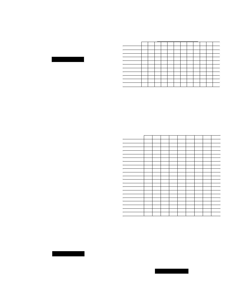
Table 7—Refrigerant Charging Label
DESIRED SUPERHEAT TEMPERATURE (F)
(Measured @ Low-Side Service Port)
OUTDOOR
AMBIENT
EVAPORATOR AIR INLET EWB (F)
EDB (F)
54
56
58
60
62
64
66
68
70
72
74
76
65
10
13
16
19
21
24
27
30
33
36
38
41
70
7
10
13
16
19
21
24
27
30
33
36
39
75
_
6
9
12
15
18
21
24
28
31
34
37
80
_
—
5
8
12
15
18
21
25
28
31
35
85
—
—
—
—
8
11
15
19
22
26
30
33
90
—
—
—
—
5
9
13
16
20
24
27
31
95
6
10
14
18
22
25
29
100
—
—
__
—
—
8
12
15
20
23
27
105
5
9
13
17
22
26
110
—
—
6
11
15
20
25
115
8
14
18
23
NOTES:
1 Dashed Areas; Do not attempt to charge system under these condi
tions or refrigerate siugging may occur
2 Add charge if actual superheat temperature is higher than chart value
and remove if lower Allow ± 3 F for tolerance
REQUIRED SUCTION-TUBE TEMPERATURE (F) vs.
DESIRED SUPERHEAT TEMPERATURE (F)
(Measured @ Low-Side Service Port)
DESIRED
SUPERHEAT
SUCTION OR LOW-SIDE
AT SERVICE
PRESSURE
PORT
(Psig)
TEMP(F)
61.5
64.2
67.1
70
73
76
79.2
82.4
8S.7
0
35
37
39
41
43
45
47
49
51
2
37
39
41
43
45
47
49
51
53
4
39
41
43
45
47
49
51
53
55
6
41
43
45
47
49
51
53
55
57
8
43
45
47
49
51
53
55
57
59
10
45
47
49
51
53
55
57
59
61
12
47
49
51
53
55
57
59
61
63
14
49
51
53
55
57
59
61
63
65
16
51
53
55
57
59
61
63
65
67
18
53
55
57
59
61
63
65
67
69
20
55
57
59
61
63
65
67
69
71
22
57
59
61
63
65
67
69
71
73
24
59
61
63
65
67
69
71
73
75
26
61
63
65
67
69
71
73
75
77
28
63
65
67
69
71
73
75
77
79
30
65
67
69
71
73
75
77
79
81
32
67
69
71
73
75
77
79
81
83
34
69
71
73
75
77
79
81
83
85
36
71
73
75
77
79
81
83
85
87
38
73
75
77
79
81
83
85
87
89
40
75
77
79
81
83
85
87
89
91
NOTE: Measure suction-tube temperature with an accurate superheat
thermocouple, or thermistor-type thermometer.
Table 5 shows heating airflow at various temperature
rises. Table 6 shows both heating and cooling airflows
at various external static pressures for Models
48KHA,KLA direct-drive units. Refer to these tables
to determine airflow for system being installed. See
Table 8 for rated cooling and heating airflows.
NOTE:
Be sure all supply- and return-air grilles are open,
free from obstructions and adjusted properly.
A WARNING
Disconnect electrical power to unit before changing
blower speed. Be sure to turn off gas supply
b e fo re
dis
connecting electrical power. Fallure to do so may cause
personal injury or death.
15