Standard, Fig. 9—burner flames, Standard fig. 9—burner flames – Carrier 48KHA User Manual
Page 11
Attention! The text in this document has been recognized automatically. To view the original document, you can use the "Original mode".
ADJUSTING BURNER AIR SHUTTERS-After burners
have operated at full input for at least 10 minutes, adjust
primary air to each burner to ensure optimum heating per
formance. Make these adjustments when unit is being
installed and during routine maintenance inspections at
beginning of each heating season. Be sure each burner is
clean and free of deposits before adjusting primary air.
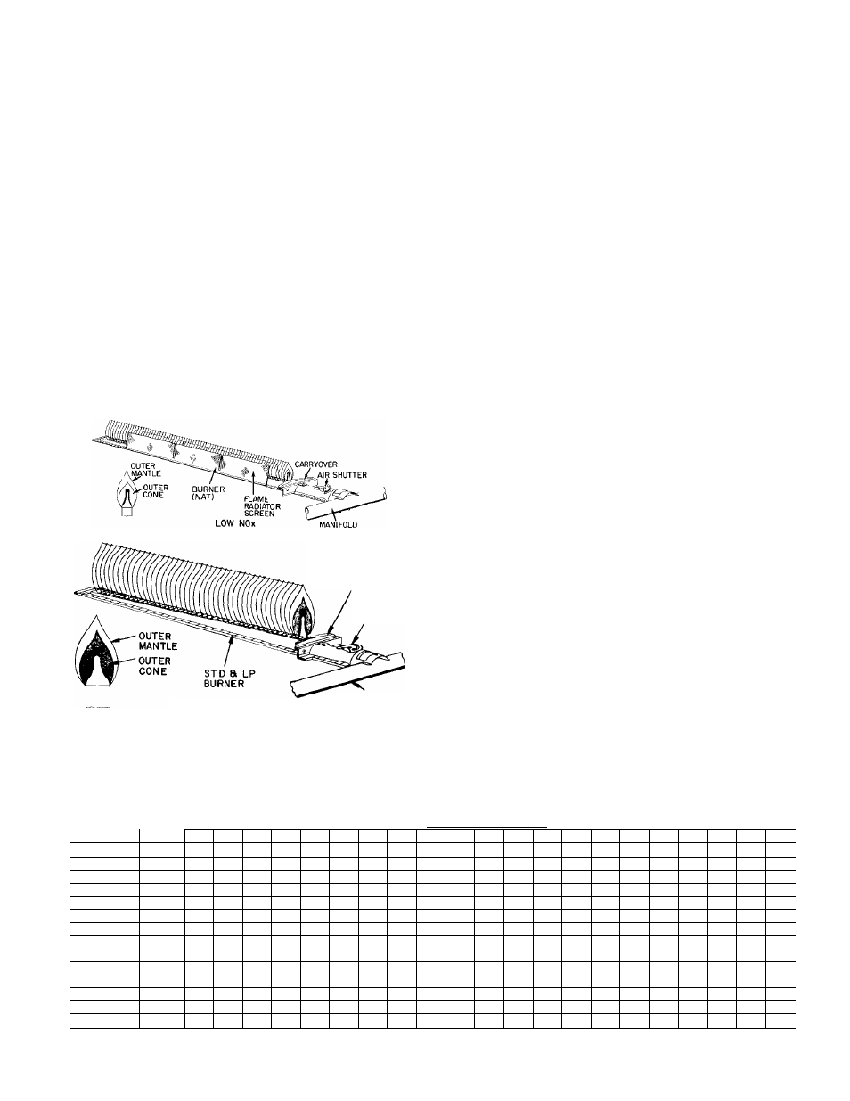
Primary air to each burner is regulated by burner air shut
ter on each burner. See Fig. 9 (Burner Flames, Standard) for
location of burner air shutter. With all burners operating,
adjust primary air to each burner as follows:
1. Loosen locking screw that secures air shutter in place
on burner, then partially close air shutter until a slight
yellow tip appears on top of burner flames.
2. Open air shutter very slowly until yellow tip just disap
pears, then secure air shutter in place with locking
screw.
3. Repeat steps 1 and 2 for each burner.
After air shutter adjustments have been completed, observe
that flames on each burner are light blue and soft in appear
ance, and that flames are same height along entire length of
each burner. See Fig. 9.
CARRYOVER
AIR
SHUTTER
STANDARD
Fig. 9—Burner Flames
MANIFOLD
BLOWER HEAT-RELAY OPERATION-Heating relay
(see Fig. 6 and unit wiring diagram) is located in the control
box and adjusts to permit either longer or shorter OFF
cycles. The ON cycle automatically adjusts as OFF cycle
changes. Adjusting level on relay is factory-set at center
position to provide optimum performance for most installa
tions. On unusual installations, or where line voltage is con
siderably above or below rated voltage, an increase or
decrease may be required for length of time blower remains
on. To increase blower operation time, move adjusting lever
toward right-hand position. To decrease blower operation
time, move lever toward left-hand position.
AIRFLOW AND TEMPERATURE RISE-The heating
section of each size of unit is designed and approved for
heating operation within temperature rise range stamped on
unit rating plate.
Table 5 shows approved temperature rise range for each
unit and air delivery (cfm) at various temperature rises.
Heating operation airflow must produce a temperature rise
that falls within the approved range. Refer to Cooling Sec
tion Start-Up and Adjustments—Indoor Airflow emd Air
flow Adjustments to adjust heating airflow when required.
HEATING SEQUENCE OF OPERATION—See Fig. 10
Models 48KHA,KLA have an intermittent electric-spark
ignition system without a standing flame. When manual
shutoff is opened, gas flows to gas valve. On a call for heat
ing by the thermostat, unit terminal R makes to unit termi
nal W. Pilot veJve solenoid of gas valve and spark generator
are energized. Gas flows to pilot and the pilot is ignited
within 4 seconds. The flame sensor proves the presence of
pilot flame within 0.8 seconds after pilot ignition. The inter
nal switching of gas valve de-energizes spark generator,
energizes meun valve solenoid and energizes heating delay
relay. Gas flows to medn burners and is ignited by pilot
flame. Contacts of heating relay close between 60 and 90
seconds after burners are ignited, and blower motor starts.
Heating cycle is now in normeil operation. Unit will continue
operating in heating cycle until thermostat is satisfied.
When this occurs, the thermostat switching removes 24-volt
control circuit voltage instantly; however, contacts of de
energized heating relay remain closed and keep blower
motor running for an additional 2 to 3 minutes. Contacts of
heating relay open after 2- to 3-minute delay and blower
motor stops. Heating section is now in a standby condition
wmting for another call for heating from thermostat.
Table 5—Air Delivery (cfm) at Indicated Temperature
Rise and Rated Heating Input
MODEL 48-
HTG
INPUT
TEMPERATURE RISE(F)
(Btuh)
35
37
39
41
43
45
47
49
51
53
55
57
59
61
63
65
67
69
71
73
75
KLA118
40,000
794
751
712
678
646
617
591
567
545
524
505
487
471
455
441
427
_
—
—
—
—
KLA124
40,000
794
751
712
678
646
617
591
567
545
KHA024
75,000
—
—
—
—
1212
1158
1109
1063
1022
983
947
914
883
854
827
809
778
—
—
—
—
KLA130
40,000
794
751
712
678
646
617
591
567
545
524
505
487
471
455
KHA030
75,000
—
—
1271
1212
1158
1109
1063
1022
983
947
914
883
854
KLA136
60,000
1190
1126
1068
1016
969
926
887
850
817
786
758
731
706
683
KHA036/136
100,000
1984
1877
1781
1694
1615
1543
1478
1417
1362
1310
1263
1218
1177
1138
1102
1068
1036
1006
978
951
926
KHA036
125,000
—
—
—
2117
2019
1930
1846
1771
1701
1638
1579
1523
1472
1423
1378
1336
1296
1258
1223
1189
1158
KLA142
60,000
1190
1128
1068
1016
969
926
887
850
817
786
758
731
706
683
661
641
622
604
587
571
556
KHA042
125,000
—
—
~
—
_
1930
1846
1771
1702
1638
1579
1523
1482
1423
1378
1326
1296
1258
1223
1189
—
KLA148
80,000
1587
1502
1425
1355
1292
1235
1182
1134
1089
1048
1010
975
942
911
—
—
—
—
—
—
—
KHA048
125,000
—
—
2326
2117
2019
1930
1846
1771
1702
1638
1579
1523
1472
1423
1378
1336
1296
—
—
—
—
KLA160
100,000
1984
1877
1781
1694
1815
1543
1478
1417
1362
1310
1263
1218
1177
1138
1102
—
—
—
_
—
—
KHA060
150,000
—
-
—
—
—
2325
2226
2135
2051
1974
1902
1835
1773
1715
1660
1609
1561
1516
1493
1483
1395
NOTE: Bolder ratings
in table fall
range of the unit Dashed areas of
below the approved temperature rise
the tabie faii beyond the air delivery
capabiiity of the unit within the operating voitage range for aii voltage
options for each size unit.
11