Electrical data – Carrier 09BB User Manual
Page 5
Attention! The text in this document has been recognized automatically. To view the original document, you can use the "Original mode".
3. A high-density fiberglass (2 lb minimum den
sity) or semirigid foamed insulation such as
Styrofoam will be required inside the ducts to
prevent air erosion. The insulation must be
firmly secured in the discharge duct near the
blower discharge to withstand the high air
velocity.
Fan Adjustment
- Check fan blade location before
start-up. Figure 6 indicates proper fan position
in relation to the fan orifice.
Fig. 6 - Position of Condenser Fan
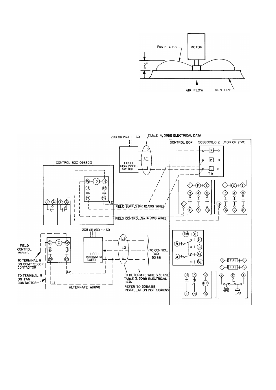
ELECTRICAL DATA
TO DETERMINE WIRE SIZE USE
O Component Connections Unmarked
O Component Connections Marked
□ Terminal Board Connections
------ Field Wiring
LEGEND
C — Compressor Contactor
HPS - High Pressure Switch
F - Fan Contactor
FU - Fuse
HR - Holding Relay
LPS - Low Pressure Switch
TB - Terminal Block
TM - Timer Motor
Fig. 7 - Typical 50BD Wiring and Component Arrangement
5