Condenser air duct insulation – Carrier 09BB User Manual
Page 4
Attention! The text in this document has been recognized automatically. To view the original document, you can use the "Original mode".
SWEAT CONNECTIONS
1. Cut tubing to length and remove burrs. Be care
ful not to expand tubing.
2. Clean tubing. Remove plug and nut from fitting.
3. IMPORTANT - Remove O ring from inside
fitting. Wrap entire valve with wet rag.
4. Insert tubing in fitting and solder with low-
temperature solder (450 F) such as Allstate
430.
INTERNAL DRAINAGE - The base pan has a
3/4-in. coupling for an interior drain outlet (for
rainwater). Remove the plug from the drain out
let and install a trap in the piping if this system
is used.
IMPORTANT: For vertical discharge unit,
provide a rain drain on back of unit (Fig. 5).
On ail units, before connecting drains trim
away insulation blocking the hole{s).
NOTE: Make solder connection at 50BB
unit, then connect to 09BB unit except for
soldering. Purge with 50B3 holding charge,
then solder.
Brackets
- After installing piping from 50BB to
09BB units, install the following:
HOT GAS LINE BRACKET - Install proper size
rubber-coated clamp assembly (furnished in 50BB
fastener package) to hot gas line bracket (Fig. 3).
CHANNEL AND PLATE ASSEMBLY - Figure 3
illustrates correct assembling and positioning for
this assembly.
Remote Piping
- For 09BB remote installation,
select pipe sizes according to length from the
following table.
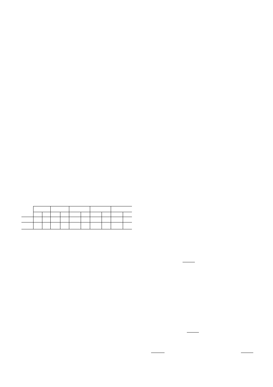
Table 2 - Remote Pipe Sizing (in.)
LENGTH OF PIPE
UINI
1
50BB
0-15 (ft)
16-25 (ft)
26-50 (ft)
51-75 (ft)
76-100 (ft)
HG
Liq
HG
Liq
HG
Liq
HG
Liq
HG
Liq
008
3/4
5/8
7/8
5/8
7/8
5/8
1
-
1/8
7/8
1
-
1/8
7/8
012
3/4
5/8
7/8
7/8
1
-
1/8
7/8
1
-
1/8
7/8
1
-
1/8
7/8
HG — Hot Gas Line
Liq — Liquid Line
NOTES;
1. Normal number of elbows and fittings have been considered in
sizing pipes.
2. Pressure loss thru recommended hot gas line check valve has
been considered for 25-100 ft lengths.
3. Use of
0
hot gas line check valve is recommended on 50BB012
units with field-supplied piping.
To connect piping, use instructions previously
given for compatible fittings. Use refrigerant
grade piping. If tubing size is other than unit con
nection sizes, use adapter fittings.
Refer to 50BB Installation Instructions to de
termine refrigerant charge adjustment for remote
piping.
Drains
- The 09BB unit provides a choice of two
drain systems for installation. The choice is gov
erned by unit location.
EXTERNAL DRAINAGE - If unit is located with
front panel outside of building, there are four
7/8-in. knockouts that can be used for external
drainage (Fig. 1).
Pitch drain pipes downward for proper drain
age. Provide tees plugged one side for cleanouts.
Leave clearance for servicing. Observe local
sanitary codes.
For other piping details refer to Carrier Sys
tem Design Manual.
Ductwork
- The 09BB unit is designed for use
without ductwork or rain louvers. If either is used,
care must be taken to eliminate air recirculation.
Recirculation can be minimized by blocking the
front discharge and discharging thru an extension
elbow. When properly designed, hinged discharge
louvers can be applied to ductwork, also to the con
denser air discharge. Fixed rain louvers over dis
charge outlets can cause excessive recirculation
and nuisance high-pressure switch cutouts. Ob
structions closer than 20 ft to the discharge air
pattern can cause significant recirculation.
If ductwork is used from standard discharge
openings and another "bird screen” is provided,
remove Carrier supplied screen to reduce static
pressure load.
CONDENSER AIR DUCT INSULATION
The condenser air duct must be insulated on
indoor installations to prevent moisture condensa
tion on the unit panels during cold weather. Insu
late as follows:
1. If metal ductwork is used, insulation should be
applied on the inside of the duct. This insulation
should be extended to cover the inside of the
09BB duct flanges.
It is necessary to insulate the inside of the
ducts at the duct flanges to reduce heat loss
from the metal cabinet by conduction thru the
duct flanges and into the cold duct. Interior
insulation allows the metal duct to approach
room temperature. It also prevents condensa
tion from forming and collecting under the in
sulation which will occur with exterior duct
insulation.
2. If insulation is applied to the outside of the
metal duct, the inside must be insulated for a
length of ten inches from the unit (including
the duct flanges) or up to the flexible duct
vapor barrier on the outside which must be
tightly sealed to prevent condensation under
the insulation.