Installation, Positioning 09bb unit, Piping – Carrier 09BB User Manual
Page 3
Attention! The text in this document has been recognized automatically. To view the original document, you can use the "Original mode".
INSTALLATION
Mounting Brackets
- Two mounting brackets are
supplied for mounting the 09 BB unit to the 50BB
unit (Fig. 4). These brackets have been designed
to provide adjustable heights for the 09BB to the
nearest 1/2 in. This is done by providing two sets
of mounting holes on the bracket, spaced 1-1/2 in.
apart. The upper mounting holes allow 09BB unit
height adjustment in 1-in. increments starting
1 ft 10-1/2 in. from the floor. The lower mounting
holes allow height adjustment in l-ir. increments
starting 2 ft from the floor.
Install brackets as follows:
1. Remove the top four retaining screws on each
side of the back panel of 50BB.
2. Select mounting holes and place bracket in
position. Install with retaining screws and
channel bolts in shipping holes (Fig. 4).
Install support bolts as shown in Fig. 3.
Install vibration isolators (supplied) in lowest
hole each side of 50BB back panel (Fig. 4). Re
move Tinnerman nut and install each vibration
isolator with 5/16 in. plain washer (supplied in
fastener package).
3.
4.
Fig. 4 - Installation of Mounting Brackets
Positioning 09BB Unit
refer to Fig. 3.
For typical installation
WARNING: The 50EB unit will not balance the
09BB unit without additional support.
Once 09BB unit has been positioned in the
mounting brackets, install locking bolts as shown
in mounting bracket detail.
Before sliding units into final position, check
for clearance to access panels, and service area
to install piping.
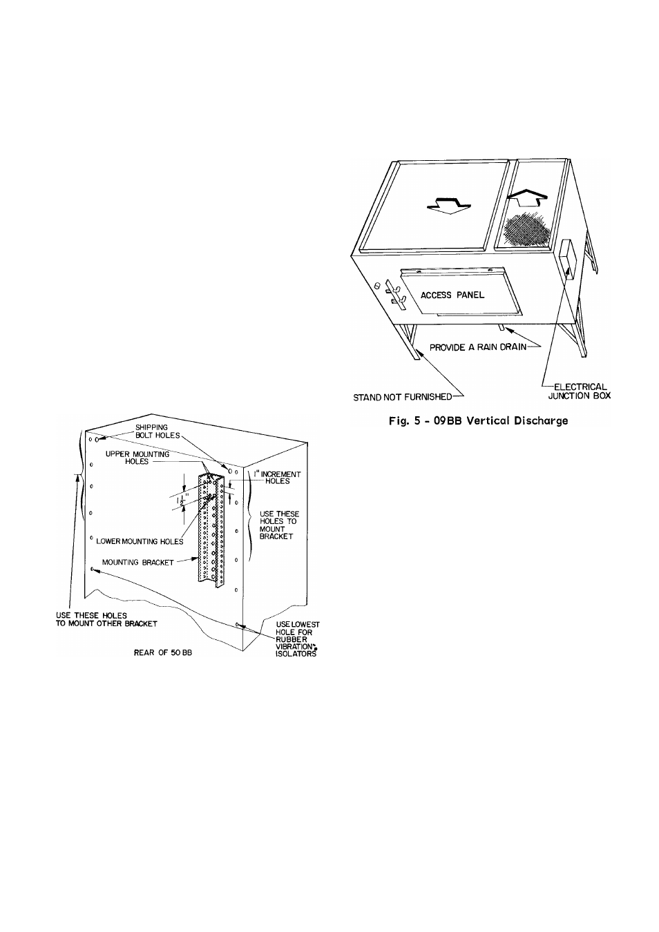
Vertical Discharge
- 09BB unit can be mounted as
shown in Fig. 5. It will be necessary to relocate
the electrical junction box either external to unit
(as shown) or on an interior panel.
Also, provide a rain drain on back of unit.
PIPING
09BB hot gas and liquid line piping is factory
supplied when field mounting the 09BB to the 50BB.
The preformed piping is arranged for various
mounting heights. Cut the vertical rise of tubes
for height adjustment. No bending is required.
09BB units are factory charged with refrig
erant. Liquid and hot gas lines are installed
as follows:
Compatible Fittings
- Liquid and hot gas lines are
installed from the 50BB unit to the 09BB unit with
Carrier compatible fittings and service valves.
These fittings may be used as sweat or mechanical
connections. Install either type as follows:
MECHANICAL CONNECTIONS
1. Cut tubing to length and remove burrs. Be care
ful not to expand tubing.
2. Remove plug from fitting and loosen nut one
turn.
3. Position tube. Remove cap and insert tube in
fitting to depth indicated on tag (1-1/4” depth
for 5/8” and 3/4” tube, 3/4” depth for 3/8”
and 5/16” tube).
4. Leave nut loose at condenser end of each tube.
Purge one line at a time using 50BB base unit
holding charge.
5. Tighten nut to a stop on unit fitting collar.
6. Open all service valves.