Service, Lubrication – Carrier 50DQ User Manual
Page 5
Attention! The text in this document has been recognized automatically. To view the original document, you can use the "Original mode".
t
SERVICE
Head Pressure Control
shuts off one outdoor air
fan at 60 ± 3 F and restarts fan at 70 ± 3 F.
Sensing device is an ambient air temperature
sensing thermostat attached to the unit compressor
compartment side panel.
Refrigerant Coils
remove dirt and debris from
indoor and outdoor coils as required.
INDOOR AIR COILS may be cleaned with a stiff
brush, vacuum cleaner or compressed air.
Access to the fan side of the indoor coil on unit
can be obtained by removing the complete indoor
air fan assembly, less motor, from unit as one
piece. To remove indoor air fan assembly;
1. Turn unit power off.
2. Loosen fan motor and remove belt.
3. Remove four screws on each end of assembly.
Gain access to journal end of air fan section
thru lower right access panel inside compressor
compartment.
4. Lift and slide complete fan assembly from unit.
5.
Reassembly is a reversal of the preceding
procedure.
OUTDOOR AIR COILS may be cleaned using a
stiff brush, vacuum or low-pressure water, steam or
air. Outdoor air fan motors are dripproof, not
waterproof.
Filters
— Clean or replace filters as required. Refer
to Table 1 for type of filters used. Filter tracks
have spacers which, when removed, permit the use
of 2-in. filters. To remove filters, remove filter
access cover on either side of unit. Slide out filters.
TO CLEAN FILTERS ^ Flush cleanable filters
with hot water or steam or soak in mild solution of
soap or detergent and water. Allow filters to dry.
Coat filters with a dust adhesive. Refer to filter
manufacturer’s instructions as required for all
other types of filters. Do not operate unit without
air filters.
Condensate Drain
— Clean annually at start of
cooling season. In winter keep drain and trap dry
or protect against freezing.
Indoor Air Fan Adjustment
— Speed (Table 1) and
alignment is factory set but is adjusted as follows:
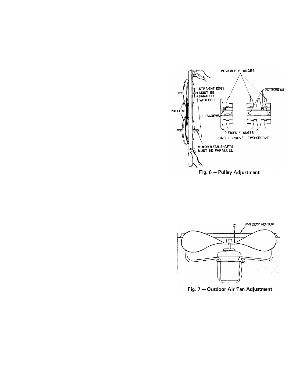
TO CHANGE FAN SPEED
1. Loosen fan belt by loosening fan motor mount
ing plate bolts.
2. Loosen pulley movable flange setscrews (Fig. 6).
3. Screw movable flange toward fixed flange to
increase speed and away from fixed flange to
decrease speed.
Increasing fan speed increases load on motor.
Do not exceed maximum fan speeds (Table 2).
4. Tighten movable flange setscrews at nearest flat
surface of pulley hub.
TO ALIGN FAN AND MOTOR PULLEYS -
Loosen fan pulley setscrews and slide fan pulley
along fan shaft. Make angular alignment by loosen
ing motor from mounting plate. Check alignment
with a straight edge (Fig. 6).
TO ADJUST BELT TENSION
1
.
2
.
3.
Loosen motor mounting plate pivot bolts.
Pull motor mounting plate up or down as
required to attain approximately 3/4-in. de
flection with one finger.
Tighten lock bolt and nut (if fitted) under
motor mounting plate to secure in fixed
position.
Outdoor Air Fan Adjustment (Fig. 7)
— Turn unit
power off. Remove fan guard and loosen fan hub
setscrews. Adjust fan height using a straight edge
laid across venturi. Tighten setscrews and cover
hub recess with rubber boot to prevent hub from
rusting to motor shaft.
Lubrication
COMPRESSOR should operate with crankcase
warm to the touch. Run unit 15 to 20 minutes or
until cooling system has stabilized. Sight glass
should be 1/2 full of oil (See Compressor Service
Instruction Manual.)
ALL FAN MOTORS AND BEARINGS are factory
lubricated and sealed. Bearings are designed to be
replaced rather than relubricated. Gain access to
journal end of evaporator air fan section thru lower
right
hand
access
panel
inside
compressor
compartment.