Fig. 5—control circuit connection (018) start-up, Fig. 6—control circuit connection (024), A caution – Carrier 38GNA User Manual
Page 4: Service, A warning, Caution, Warning
Attention! The text in this document has been recognized automatically. To view the original document, you can use the "Original mode".
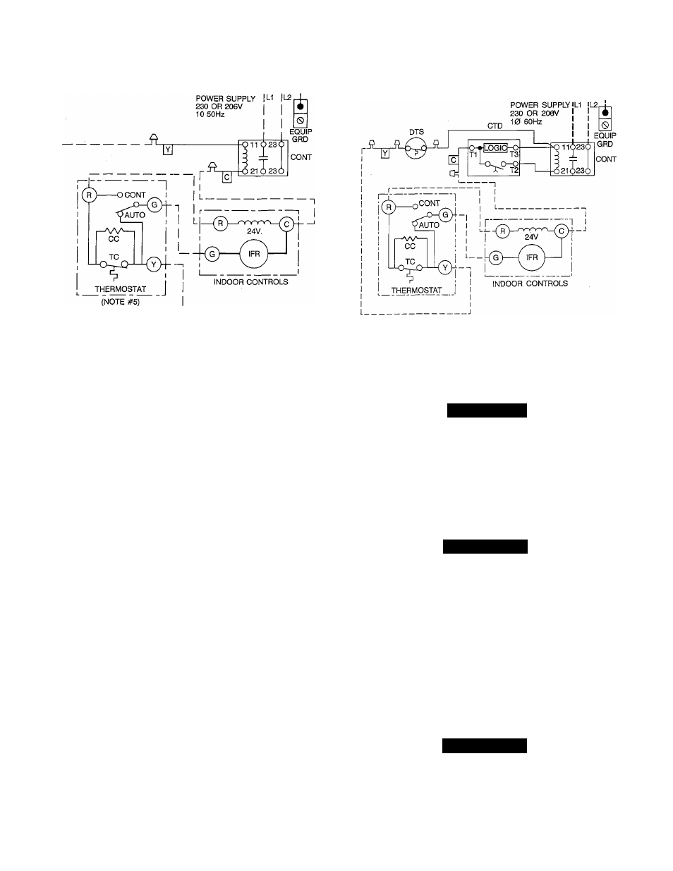
CONT CONTACTOR
IFR INDOOR FAN RELAY
CC COOLING COMPENSATOR
TC THERMOSTAT COOLING
---------- FACTORY CONTROL WIRING
---------- FIELD POWER WIRING
---------- FIELD CONTROL WIRING
O COMPONENT CONNECTION
FIELD SPLICE
A92407
Fig. 5—Control Circuit Connection (018)
START-UP
Step 1—Start-up Procedure
1. Back seat (open) liquid and suction line service valves.
2. Set thermostat selector switch at OFF.
3. Set room thermostat to desired temperature.
4. Close electrical disconnects, energizing entire system.
5. Set room thermostat at COOL and fan switch as desired, FAN
or AUTO. Operate unit for 15 minutes, then check system
refrigerant charge. See Refrigerant Charging section.
Motors and controls operate satisfactory in the 253-v/187-v range.
Do not connect charging hoses during initial start-up procedure.
(Loss of charge from this procedure may result in capacity
reduction.) If necessary to add manifold gages for servicing, refer
to the service manual for bypass method of returning charge to
system.
Step 2—Sequence of Operation
When thermostat "calls for cooling," thermostat contacts close,
energizing contactor holding coil from 24-v external power source.
Contacts close, energizing compressor motor and condenser fan
motor with supply voltage.
When thermostat is satisfied, contacts open, de-energizing contac
tor holding coil and, in turn, breaking supply voltage circuit. All
motors should stop. In 024 size applications the lock-out relay
prevents restart for up to 5 minutes. Refer to presale literature.
Step 3—Refrigerant Charging
Refer to information on unit rating plate.
CTD - COMPRESSOR TIME DELAY
IFR - INDOOR FAN RELAY
DTS - DOME THERMOSTAT
CONT - CONTACTOR
FACTORY WIRING
FIELD WIRED
POWER WIRING
SPLICE CONNECTION
A88547
Fig. 6—Control Circuit Connection (024)
A
CAUTION
To prevent personal injury, wear safety glasses and gloves
when handling refrigerant. Do not overcharge system. This
can cause compressor flooding.
SERVICE
Access to all controls and unit components is through rear access
panel.
A
WARNING
Because of possible damage to equipment or personal injury,
maintenance should be performed by a trained technician.
Consumer service is recommended only for filter cleaning/re-
placement.
Minimum maintenance to be performed:
1. Check condenser coil for cleanliness each month during
cooling season. Clean as necessary but at least once at
beginning of each season.
2. Check blower motor and wheel for cleanliness and proper
lubrication each cooling season. Clean as needed.
3. Check electrical connections for tightness and controls for
proper operation each cooling season. Service as necessary.
A
WARNING
As with any mechanical equipment, personal injury can result
from sharp metal edges, etc., therefore, be careful when
removing parts.
NOTE:
Never operate unit more than 2 minutes with rear door
removed as unit damage may result.