Step 1—make opening in wall, Step 2—make piping connections – Carrier 38GNA User Manual
Page 2
Attention! The text in this document has been recognized automatically. To view the original document, you can use the "Original mode".
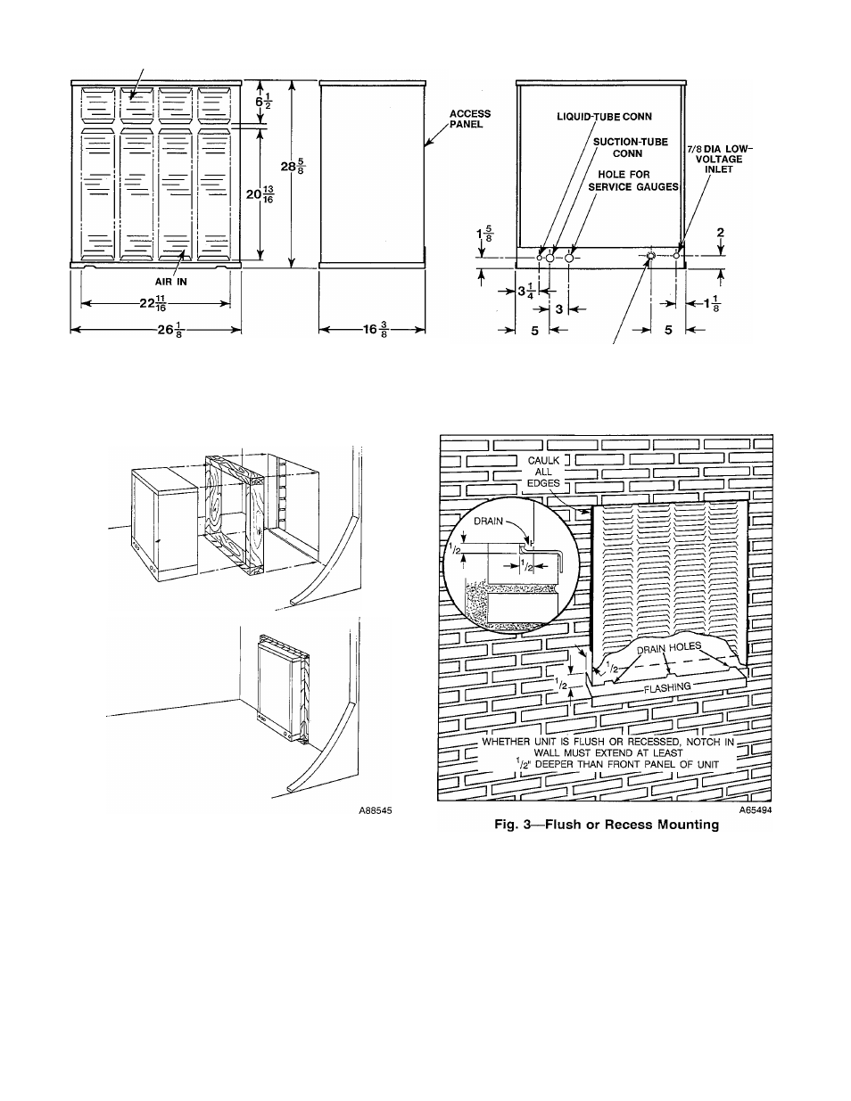
AIR OUT
7/8 DIA HOLE & 1-3/32 DIA K.O.
POWER INLET
A75135
Fig. 1—Dimensions and Connections
Fig. 2—Roughing-ln Supporting Frame
Step 1—Make Opening in Wall
Make an opening approximately 26-1/2 x 29 in. in a wall as close
to the cooling unit as possible. Build a frame to support the
condensing unit. (See Fig. 2.)
1. Insert condensing unit with frame into the wall opening.
2. Extend unit approximately 1 in. beyond outside (finished) wall
and tilt to the outside to allow rainwater to drain off. (See Fig.
3.)
3. Fasten unit to frame with metal straps.
4. Use flashing under unit and caulk all edges to provide
weathertight seal. (See Fig. 3.)
Step 2—Make Piping Connections
SELECT
CORRECT
LIQUID
AND
SUCTION
LINE
LENGTHS/DIAMETERS - Refer to Table 2.
INSTALL REFRIGERANT LINES — The condensing unit is
fully charged at the factory. Be sure both service valves are front
seated (turned clockwise) to avoid loss of charge.
Do not remove
refrigerant line connection seals from condensing unit, matching
coil, or refrigerant tubing until ready to make actual connection at
point of seal.
(M>