Installation step 1 — install motor, A warning – Carrier 38AK User Manual
Page 2
Attention! The text in this document has been recognized automatically. To view the original document, you can use the "Original mode".
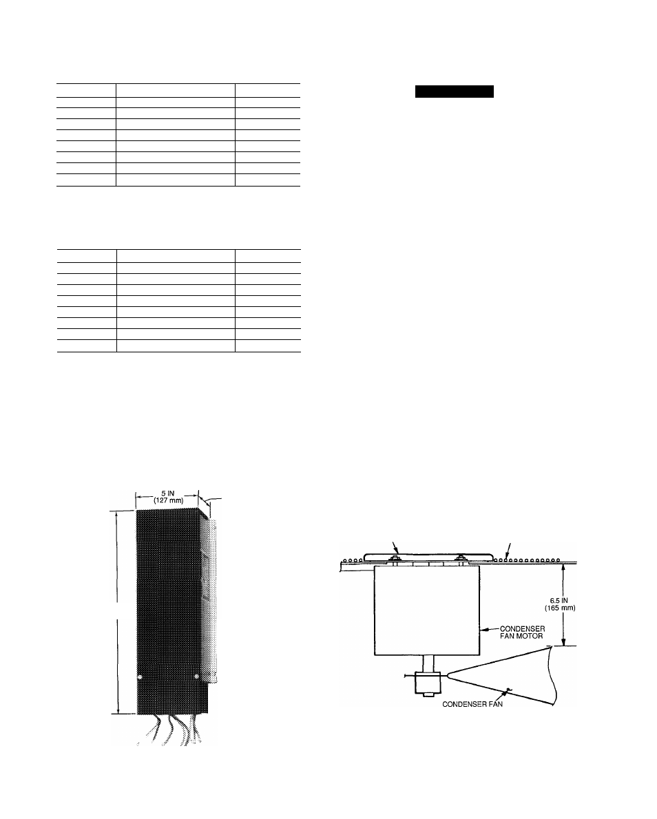
Table 2 - Motormaster® III Control Package
CAMOTOR3001A00, 208/230 v, 60 Hz and 220 v,
50 Hz Applications
QUANTITY
ITEM
PART NO.
1
Motormaster III Control
HR46GN001
1
Sensor
30GT412176
1
Motor
HD52GK208
8
Screw (5/16-In.)
AL81AS216
1
Relay
HN61KZ024
2
Screw (no. 6 — 20 X 3/4-ln )
AL56AU128
1
Bracket
50DK507132
1
Socket
HY07RB030
Table 3 — Motormaster III Control Package
CAMOTOR3002A00, 460 and 575 v, 60 Hz and
400
V,
50 Hz Applications
QUANTITY
ITEM
PART NO.
1
Motormaster III Control
HR46GN001
1
Sensor
30GT412176
1
Motor
HD52GK460
8
Screw (5/16-in )
AL81AS216
1
Relay
HN61KZ024
2
Screw (no. 6 — 20 X 3/4-in.)
AL56AU128
1
Bracket
50DK507132
1
Socket
HY07RB030
Before Installing
— inspect the contents of the acces
sory package before installing. File a claim with the ship
per if shipping damage is found. Contact the Carrier dis
tributor if a part is missing.
3 1/4
IN.
(83 mm)
16 IN
(406 mm)
MOUNTING
BASE
/
INSTALLATION
Step 1 — Install Motor
A
WARNING
To avoid the possibility of electrical shock, open all
disconnects
before
installing
or
servicing
this
accessory.
1. Shut off unit power supply.
2. Remove unit access panel and control box cover.
3. Disconnect fan motor connection in control box and
remove motor leads from control box.
4. Remove condenser fan assembly (grille, motor, motor
cover, and fan) by removing the 6 grille holddown screws.
5. Loosen fan hub set screws and remove condenser fan
from motor shaft.
6. Carefully lift off motor cover.
7. Remove the 4 holddown nuts that attach the motor to
the grille. Pull the motor wires through the grille
conduit.
8. Cut back the steel conduit on the grille (one grille wire
width) to allow adequate space for new fan motor.
9. Feed the Motormaster III motor wires through the con
duit and install motor from accessory kit onto grille us
ing nuts from Step 7.
10. Replace the motor cover on the grille using the square
cutouts.
11. Replace condenser fan on motor shaft.
12. Adjust fan height as shown in Fig. 2.
13. Tighten set screws on fan hub to 7 ft-lbs (9.52 N-m
[newton-meters]) ± 1 ft-lb (1.5 N-m).
NOTE: On 48HJ009 and 48HJ/TJ014 units, perform Step 2
— Install the Motormaster III Controller through Step 4 —
Make Electrical Connections, before reinstalling the con
denser fan. Motormaster III installation is done through the
condenser fan opening with the fan and motor removed.
14. Reinstall condenser fan assembly onto unit using screws
from Step 4. Torque to 20 in.-lbs (2260 mN-m)
± 2 in.-lbs (226 mN-m).
15. Pull motor wires completely through conduit.
MOTOR COVER
OUTLET GRILLE
Fig. 2 — Condenser Fan Height Adjustment
Fig. 1 — Motormaster III Control