Step 2 — install motormaster® iii controller, A caution, Step 3 — install sensor – Carrier 38AK User Manual
Page 3: Lh izzi
Attention! The text in this document has been recognized automatically. To view the original document, you can use the "Original mode".
Step 2 — Install Motormaster® III Controller
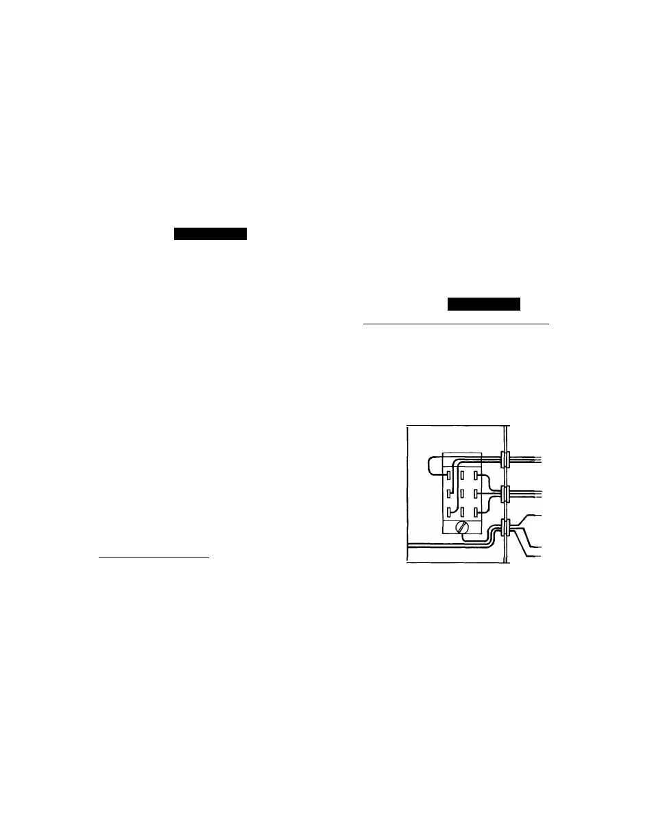
1. Configure the control signal selection switch. Remove
the cover of the Motormaster III control. Set the switch
on the Motormaster III control board (underneath cover)
to accept the thermistor (sensor) input signal. Set the
frequency switch to match the unit power supply (50 Hz
or 60 Hz). See Fig. 3 for switch locations and proper
position. Replace the cover.
2. 38AK008.012; 38AKS008-012; 48HJ008,012; 48TJ008-
012; 50HJ/TJ008-014; AND 50UQ008,012; UNITS WITH
SINGLE POINT BOX: Mount the Motormaster III con
troller on the unit in the location specified in Fig. 4-6.
The controller must be mounted vertically with the leads
at the bottom. Using the template provided on the last
page of the book, mark the 4 mounting hole locations.
Mount the controller using the Yie-in. self-drilling screws
provided.
A
CAUTION
To avoid damaging components and wiring, use ex
treme care when drilling screw holes and screwing
in fasteners.
50HJ/TJ008-014 AND 50LJQ008,012 UNITS WITH
OUT SINGLE POINT BOX; 48HJ009 (208/230
AND 460 V); AND 48HJ/TJ014 UNITS: Mount the
Motormaster III controller on the unit in the location spec
ified in Pig. 7 and 8. The controller must be mounted
vertically with the leads at the bottom. Using the tem
plate supplied on the last page of the manual, mark the
4 mounting locations. Mount the controller using the
yi6-in. self-drilling screws provided. To prevent any
water leakage though the bulkhead (the partition sepa
rating the indoor and outdoor sections), an electric
component compatible, general purpose silicon rubber
sealant must be used along the 4 edges of the controller
and at the 4 mounting-screw locations.
38AQS008 AND 48HJ009 (575 V) UNITS: The
Motormaster III controller must be mounted on a sheet
metal bracket provided. Mount the bracket on the unit
in the location specified in Fig. 9 and 10 using four
yi6-in. self-drilling screws provided. If needed, a bracket
mounting template is provided on page 21. The control
ler must be mounted vertically, with the leads at the
bottom. Mount the controller on the bracket using the
remaining four 5/16-in. self-drilling screws. See Fig. 11
for controller mounting details.
Step 3 — Install Sensor
38AK008,012; 38AKS008-012 AND 48/50HJ,TJ008-014
UNITS — Install the sensor for thermistor input control on
the header tube designated in Fig. 12. Connect the sensor
leads to the violet and gray control signal leads on the
Motormaster III controller. Wrap and tie excess sensor wir
ing. Refer to Step 4 — Make Electrical Connections and
the unit wiring diagram for more information on wiring the
sensor.
A
CAUTION
I Sensor assembly is delicate. Handle with care. |
38AQS008 AND 50LJQ008,012 UNITS - Wiring is field-
supplied. Wiring must be 16 AWG (American Wire Gage)
(1.5 mm^), appliance wiring material, rated 75 C or its equiv
alent, with %4-in. (.8 mm) minimum insulation thickness.
All wiring must comply with NEC (National Electrical Code)
and applicable local codes.
50 HZ
,(o^
PHASE SEQUENCE
INDICATOR
ADJUST SWITCH
TO MATCH LINE
FREQUENCY
60 HZ
ADJUST SWITCH TO
\ MATCH INPUT
k CONTROL SIGNAL
CONTROL INPUT
___ CE]__________
□
LH izzi
□
(SENSOR) THERMISTOR* 4 - 20 mA
LEADS TO POWER
SOURCE
BLACK LI
BLUEL3 -
YELL2
LEADS TO
MOTOR
GRN (GND)
CONTROL
SIGNAL
LEADS
+VIO
-GRAY
3 HOLES 0 88 DIA (FOR 1/2 IN CONDUIT)-
LEGEND
GND
— Ground
*For thermistor (sensor) signal, move switch to the left.
NOTE: Thermistor is designated in text as “sensor.”
Fig. 3 — Motormaster III Control Signal Selection Switch