Troubleshooting – Carrier 38AK User Manual
Page 17
Attention! The text in this document has been recognized automatically. To view the original document, you can use the "Original mode".
TROUBLESHOOTING
1. The Motormaster® III control must be securely grounded
to the cabinet of the unit to function properly.
2. The power frequency switch must be in the correct
position for the power supply being used. The control
switch must be set at the thermistor setting.
3. Motormaster III controls may be applied only to spe
cially qualified fan motors. Ensure that the proper fan
motor has been installed with the Motormaster III con
trol. See Tables 2 and 3.
4. A true RMS (Root Mean Square) meter is required to
accurately read the output from the Motormaster III
control because of the electronically controlled output
voltage.
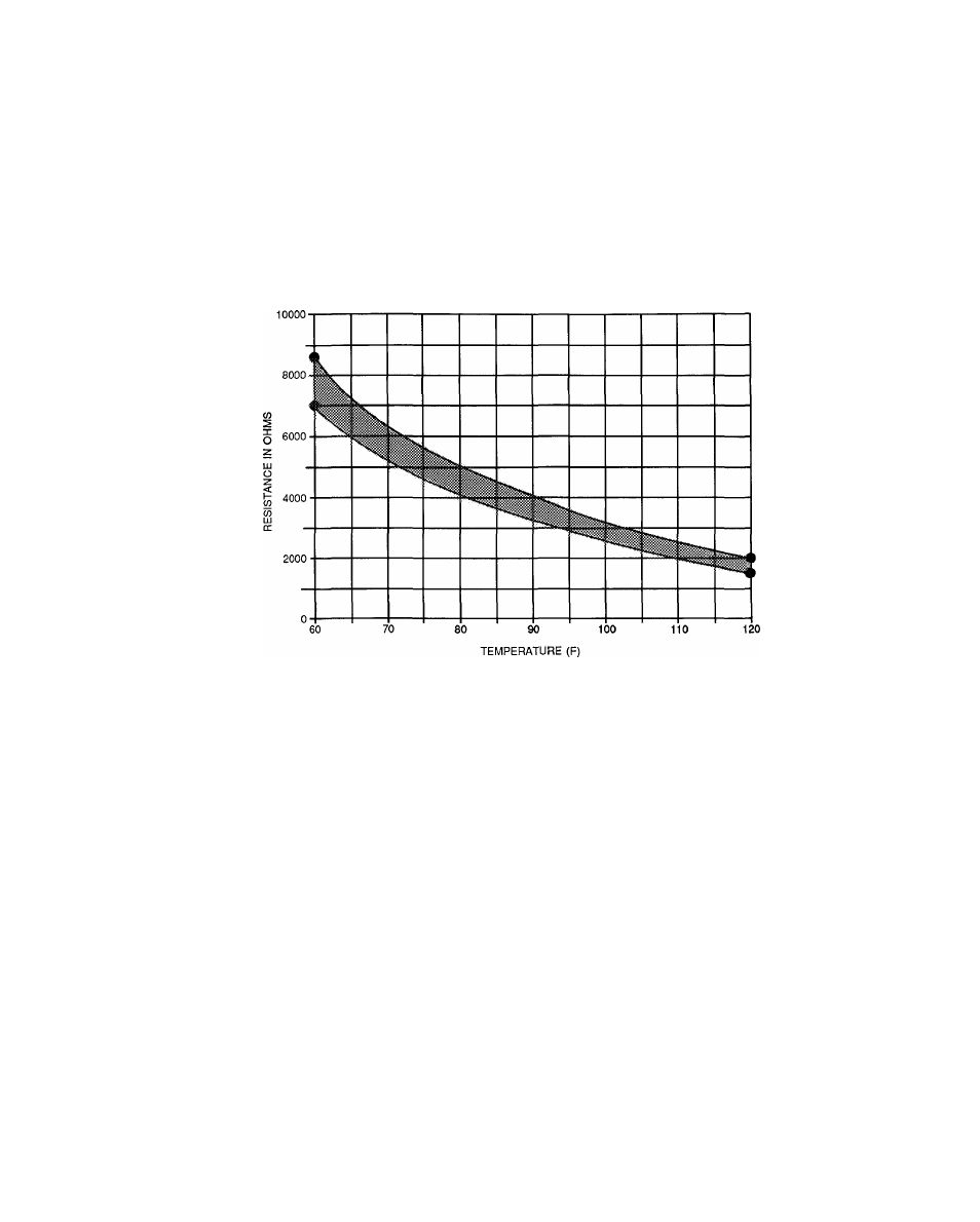
5. Thermistor sensor lead connections should be carefully
rechecked if there is an operational problem. See the
thermistor characteristic for sensor 30GT412176 shown
in Fig. 31. The controller operates between 1600 ohms
and 5800 ohms. At 1600 ohms the controller is at full
voltage. At 5800 ohms the output is at a minimum (10%
of motor speed).
15
20
40
25
30
35
TEMPERATURE (C)
LEGEND
¡Tolerance band for allowable Motormaster III resistance values.
Fig. 31 - Thermistor Resistance vs Temperature
45
50
17