Carrier 38AK User Manual
Page 10
Attention! The text in this document has been recognized automatically. To view the original document, you can use the "Original mode".
C0.
+® (3) +
CD (D
IF&
cx
EES ®
MOTORMASTER III RELAY
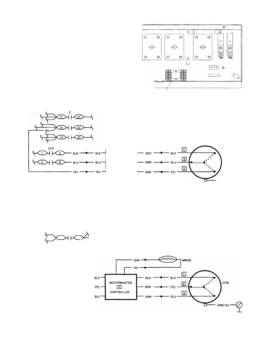
Fig. 15 — Motormaster® III Relay Location
38AQS008
MOTORMASTER III RELAY
Fig. 16 - Motormaster ill Relay Location
50LJQ008,012
GRA—•-
VIO •
MMSN
MOTORMASTER
m
CONTROLLER
LEGEND
C
— Compressor Contactor
MMSN
— Motormaster Sensor
OFC
— Outdoor-Fan Contactor
OFM
— Outdoor-Fan Motor
NOTES;
1. On 50 Hz units, disconnect yeliow wire connected to Terminai 6
of the outdoor fan contactor (OFC). Tape wire and secure in
side control box
2. See wiring label on unit for more details.
OFM
GRN-YEL-
-9
Fig. 17 - Fan Power Wiring - 38AKS009,012 - 208/230 V, 460 V; 60 Hz and 220 V, 400 V; 50 Hz
(
13
23^
BLK
• YEL
BLU
□
LEGEND
C
— Compressor Contactor
MMSN
— Motormaster Sensor
OFM
— Outdoor-Fan Motor
NOTES:
1. On 50 Hz units, disconnect yellow wire connected to Termi
nal 22 of the compressor contactor (C). Tape wire and se
cure inside control box.
2. See wiring label on unit for more details
Fig. 18 - Fan Power Wiring - 38AK008,012; 38AKS008 -208/230 V, 460 V; 60 Hz and 220 V, 400 V; 50 Hz
10