Step 6 — make txv adjustments, Start-up, Sequence of operation – Carrier 40RR024 User Manual
Page 5: Cooling
Attention! The text in this document has been recognized automatically. To view the original document, you can use the "Original mode".
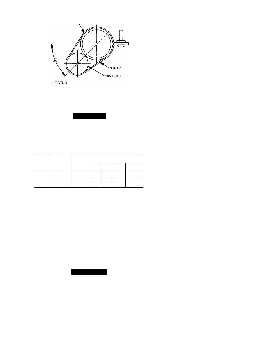
VAPOR LINE
TXV
— Thermostatic Expansion Valve
NOTE: The 8 o’clock position is shown above
Fig. 5 — TXV Feeler Bulb Locations
Step 6 — Make TXV Adjustments.
A
CAUTION
Wait 30 minutes between TXV adjustments to avoid
excessive superheat.
Make TXV adjustments on 40RR after installation of pip
ing package, verifying 10° F superheat.
Table 4 — Unit 40RR Electrical Data
UNIT
V*-PH-HZ
VOLTAGE
FAN
MOTOR
POWER
SUPPLY
LIMITS
Hp
FLA
MCA
MOCP
(Amps)
40RR
024
208-3-60
180-220
3
10.8
132
15
230-3-60
207-253
3
10.1
11.5
15
460-3-60t
416-528
5.0
58
LEGEND
FLA
— Full Load Amps
MCA
— Minimum Circuit Amps
MOCP
— Maximum Overcurrent Protection
‘Motors are designed for satisfactory operation at ± 10% of nominai
voitages shown. Voitages should not exceed the limits shown in the
“Voltage Limits” column.
fMotors must be field wired for 460 v in accordance with directions
on nameplate of motor.
NOTE: Fan motors are field supplied on unit 40RR024 (575 v) and
on 50-Hz units.
NOTE: Because this split system uses TXV’s in the heating
cycle, refrigerant charge can be adjusted during heating op
eration. When properly charged, the 40RR has approxi
mately 32° F of state point subcooling leaving circuits no.
1 and 2 from the indoor coil in the heating cycle. Use charg
ing chart on unit to complete charging (in cooling cycle
only).
NOTE: Use refrigerant R-22 only.
NOTE: Since the 38QP unit contains 2 refrigeration
circuits, both circuits must be charged separately.
To charge system:
1. Regulate valve at refrigerant (R-22) tank to maintain suc
tion pressure at 80 psig (551.6 kPa) while charging. Charge
with vapor only at suction side of unit.
NOTE: Do not depend on sight glass when charging unit;
use charging charts which are attached to the inside of each
compressor access panel.
2. Measure line temperature close to the liquid service valve,
and measure the pressure at the Schrader port on the liq
uid line service valve. Plot point on the charging chart.
If point is above the line, add charge. If point is below
the line, remove and reclaim charge until operating point
falls on the curve.
3. Allow system to operate for 20 minutes. Take tempera
ture and pressure reading at liquid service valve and check
values with the charging chart.
4. Record final installed system charge in ink on unit
nameplate.
CHECK OIL CHARGE — Allow system to run for approx
imately 20 minutes. Stop system and check compressor oil
level. Ten pints is the proper oil charge amount for a 6D
compressor. Add oil only if necessary to bring oil into view
in sight glass. Use only Carrier-approved compressor oil:
Petroleum Specialties .......................................... Cryol 150A
Texaco, Inc....................................................... Capella WE32
Witco Chemical Corp......................................... Sunisco 3GS
IMPORTANT: Do not reuse drained compressor oil
or oil that has been exposed to atmosphere. Proce
dures for adding oil are given in GTAC II, Module 5,
Charging, Recovery, Recycling, and Reclamation. To
remove oil: shut system off; isolate the compressor;
remove and reclaim the refrigerant in the compressor;
remove the compressor oil drain plug.
START-UP
Evacuate and Dehydrate
— Evacuate and dehy
drate entire refrigerant system as shown in General Train
ing Air Conditioning (GTAC) II, Module 4, System
Dehydration.
A WARNING
To prevent personal injury, wear safety glasses and gloves
when handling refrigerant. Do not overcharge system
— this can cause compressor flooding. Never charge
liquid into the low-pressure side of the system. During
charging or removal of refrigerant, be sure indoor fan
system is operating.
Preliminary Charge
— Refer to GTAC II, Module 5,
Charging, Recovery, Recycling, and Reclamation for charg
ing methods and procedures. Charge system per Table 1 in
GTAC II by the liquid charging method and charging by
weight procedure.
Charge System (Cooling Only)
— Refer to GTAC
II, Module 5, Charging, Recovery, Recycling, and Recla
mation, and the following procedure.
SEQUENCE OF OPERATION
General
— The heat pump contains 2 independent re
frigeration circuits. Each circuit has its own set of indepen
dent controls, compressor, liquid line solenoid valve, re
versing valve, crankcase heater, TXV, and accumulator.
Circuit breakers provide overcurrent protection for com
pressors (in both heating and cooling modes). These re
quire manual reset at the 38QP unit control box. The oil
pressure safety and crankcase heater also require reset at
the outdoor unit.
Cooling
NOTE: When power is supplied to a system that is off,
crankcase heaters are energized. The reversing valve may
or may not be energized depending on mode of operation
(heating or cooling) when thermostat was previously
satisfied.
The following cooling operating sequence has both heat
pump circuits connected to a single, 2-circuit fan coil. The
system is controlled by a single 2-stage heat/2-stage cool
thermostat.