Carrier 40RR024 User Manual
Page 4
Attention! The text in this document has been recognized automatically. To view the original document, you can use the "Original mode".
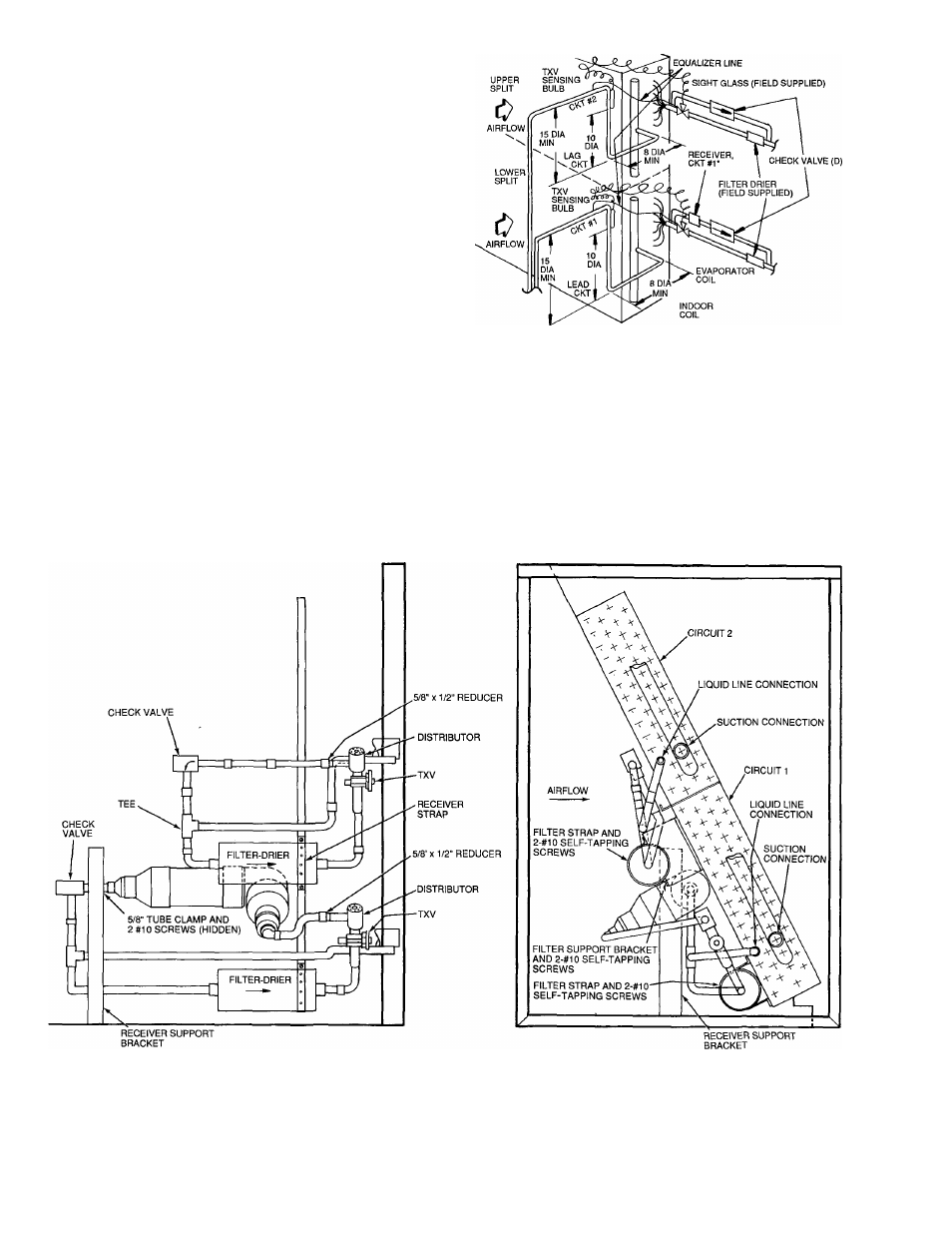
Step 4 — Install Piping Package — install parts of
piping package as shown in Fig. 3.
CONNECT LIQUID AND VAPOR LINES - Run liquid
and vapor lines separately between the 38QP and the 40RR
units, because the 38QP has dual independent refrigerant
circuits. A label on the 38QP comer post identifies the
circuits.
CONNECT EQUALIZER LINE TO EACH THERMO
STATIC EXPANSION VALVE (TXV) - (See Fig. 4.)
Install a fitting for suction pressure readings near the indoor
section to allow for TXV superheat adjustments. (A fitting
can be installed in the equalizer line for this purpose.)
MOUNT TXV SENSING BULB - Locate TXV sensing
bulb on the suction line as shown in Fig. 4. Do not attach
bulb to suction manifold (header). Locate bulb on a vertical
riser where possible. If a horizontal location is necessary,
secure the bulb at approximately 4 o’clock or 8 o’clock
position. (See Fig. 5.)
Step 5 — Connect Power Wiring — All wiring
must comply with local and National Electrical Code re
quirements. See the installation instructions with each in
door and outdoor unit for recommended wire and fuse sizes.
See 38QP wiring book for wiring diagrams and Table 4 for
40RR wire MCA (minimum circuit amps) and MOCP (max
imum overcurrent protection). Perform charging instruc
tions per installation instructions provided with the outdoor
unit.
‘40RR024 Only.
Fig. 4
Equalizer Line and TXV Sensing Bulb
Locations
TXV
— Thermostatic Expansion Valve
NOTE: Cut distributor side outlet tube to 1-5/16 in. (33.3 mm) length from OD of distributor.
Fig. 3 — Unit 40RR Piping Arrangement