Accessories, Installation, Step 2 — size piping lines — employ one of the – Carrier 40RR024 User Manual
Page 2: Step 3 - check contents of piping package
Attention! The text in this document has been recognized automatically. To view the original document, you can use the "Original mode".
Accessories
PIPING PACKAGE — Contains check valves, thermo
static expansion valves (TXV’s), receiver, filter driers, and
tubing to connect the indoor coils for heat pump service.
THERMOSTAT HH07AT172 (HH07AT162 For Use on
Celsius Scale) — Used with subbase HH93AZ174, is a 2-stage
cool/2-stage heat thermostat with automatic changeover and
a lockout light. There is no provision for emergency heat.
THERMOSTAT HH07AT172 (HH07AT162 For Use on
Celsius Scale) — Used with subbase HH93AZ177, is a 2-stage
cool/2-stage heat thermostat. This combination has all the
features of HH07AT172 (HH07AT162)/HH93AZ174 plus
a provision for emergency heat.
SEQUENCER PACKAGE — Can be used with this system
when unloaders are added to the compressor(s). (Unloading
can be applied in the cooling cycle only. Unloading can
never be applied in the heating cycle.) The sequencer has
4-stage cooling capability.
ELECTRIC HEATERS — May be used with the 40RR in
door unit (see Table 1). Use a maximum of four 20-kW
(at 240 v) or 21.8-kW (at 480 v) electric heater assemblies.
ELECTRIC HEATER CONTROL PACKAGE 40RT900081
— Provides control for up to 3 stages of electric heat when
used with outdoor-air thermostat(s). Package must be used
whenever 40RT electric heaters are utilized. If a fourth
stage of electric heat is used, an additional field-supplied
heater control relay is necessary. This relay must have a
24-V coil with 230-v contacts. Outdoor thermostats
(part no. HH22QA040) are recommended for staging elec
tric heaters.
Table 1 — Unit 40RR Accessory Electric Heaters
ELECTRIC HEATER (3 PHASE 50/60 Hz)
PART NO.
Rated
Voltage
kW
FLA
40RT-900-101
240
20.0
48 0
40RT-900-111
480
21.8
26.0
LEGEND
FLA —
Full Load Amps
NOTES;
1. A maximum of 4 electric heaters can be used with the 40RR024
unit.
2 Electric heaters are not UL (Underwriters’ Laboratories) listed for
the 38QP/40RR heat pump.
WATTAGE MULTIPLICATION FACTORS
Heater Voltage
Rating
Actual Heater
Voltage
(3 Phase, 50/60 Hz)
Multiplication
Factor
200
0.69
208
0.75
240
220
0.84
230
0.92
240
1.00
380
0.63
400
0 69
480
415
440
0.75
0.84
460
0.92
480
1.00
INSTALLATION
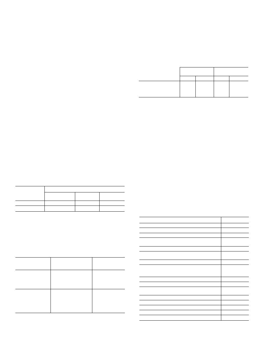
Step 1 — Perform Outdoor and Indoor Unit
Installation — Follow the installation instructions pro
vided with each outdoor and indoor unit. See Table 2 for
maximum vertical elevation between the indoor and out
door sections.
Table 2 - Maximum Vertical Separation
HEIGHT OF INDOOR UNIT
SYSTEM
Above Outdoor
Unit
Below Outdoor
Unit
ft
m
ft
m
40RR024/38QP024,
60 Hz, Ckt 1 and 2
40RR024/38QP024,
50 Hz, Ckt 1 and 2
59
58
180
17.7
59
58
18.0
17.7
Step 2 — Size Piping Lines — Employ one of the
following methods to size interconnecting refrigerant pip
ing between the 38QP and the 40RR:
1. Use the pipe sizes shown in Refrigerant (R-22) Charge
and Piping Selection table in the 38QP installation in
structions (when not using field-installed accessory un
loaders).
2. Use the Carrier System Design Manual, Part 3, Piping
Design
(when
using
field-installed
accessory
unloaders).
3. Use the piping sizing portion of the Carrier E20-II com
puter program (when using field-installed accessory
unloaders).
NOTE: Liquid line solenoid valves are not required; they
are factory-installed on the 38QP.
Step 3 - Check Contents of Piping Package
— Install heat pump piping package to convert indoor coil
for heat pump service. Table 3 lists the contents of the pip
ing package. Figure 2 shows the contents of the piping pack
age in the approximate order in which they are installed.
Table 3 — Heat Pump Piping Package Contents
Example: 20.0 kW (at 240 v) heater on 230 v
= 20.0 (0.92 multiplication factor)
= 18.4 kW capacity at 230 v
DESCRIPTION
QUANTITY
Receiver, Piping Assy (Ckt 1)
1
Piping Assy (Ckt 2)
1
Filter Drier (Ckt 1 and 2)
2
Receiver, Piping Assy Support Bracket
(Cktl)
1
Filter Drier Support Bracket (Ckt 2)
1
TXV (Thermostatic Expansion Valve)
(Ckt 1 and 2)
2
Screw, Receiver Strap*
1
Screws, No. 10 for Filter Drier Strap (4)
5/8" Tube Clamp (2), Filter Drier Support
Bracket (2)*
8
Tube, Filter Drier to TXV (Ckt 1)
1
Tube, Filter Drier to TXV (Ckt 2)
1
Strapping, 11" Long for Filter Driers
(Ckt 1 and 2)
2
Strapping, 10" Long for Receiver (Ckt 1)
1
Clamp for 5/8" OD Tube (Ckt 1)
1
Installation Instructions*
1
Strap for TXV Sensort
2
Screw and Nut for TXV Strapt
2
‘Items are included in a packet which accompanies piping package,
titems are packed together with TXV.