Schematic wiring diagram — condenser control, Head pressure control, Head pressure control data – Carrier 09DC User Manual
Page 4: Abs,ï2, 43 s2
Attention! The text in this document has been recognized automatically. To view the original document, you can use the "Original mode".
General
—
Efficient
operation
of
evaporator
expansion
valves
requires
a
90
F
minimum
condensing
temperature
for
100%
compressor
capacity,
80
F
for
75%
capacity,
and
70
F
for
50%
and
25%
capacity.
The
capacity
of
an
air-cooled
condenser
increases
with
increased
temperature
difference
(cond
temp
minus
entering
air
temp)
and
decreases
with
decreased
temperature
difference.
Therefore,
a
drop
in
en
tering
air
temperature
lowers
the
condensing
temperature
for
a
given
heat
rejection.
When
outdoor
air
temperatures
drop
below
prescribed
minimums,
some
form
of
head
pres
sure
control
is
required.
(See
Head
Pressure
Control
Data
table
for
minimum
outdoor
temperatures
and
specific
head
pressure controls for 9AB and 09DC units.)
HEAD PRESSURE CONTROL
9AB, 09DC Head Pressure Controls
— Head pressure on
9AB
and
09DC
condensers
may
be
controlled
by
the
Motor-
master
Electronic
Control,
by
fan
cycling,
or
by
fan
cycling
supplemented by the Motormaster or a modulating damper.
Motormaster
—
When
outdoor
temperatures
are
low
enough
to
cause
low
condensing
pressures,
the
Motormaster
modu
lates
the
motor
speed
of
one
condenser
fan
from
full
to
zero
rpm
to
maintain
a
constant
saturated
condensing
tempera
ture.
The
Motormaster,
available
only
with
single-phase
motors
(on
unit
sizes
thru
09DC016),
may
be
the
sole
con
trol
on
single
fan
units
or
may
be
used
in
conjunction
with
fan
cycling
control
on
multiple
fan
units
for
full
year-round
head pressure control.
Fan
Cycling
—
The
fan
cycling
control,
used
primarily
during intermediate seasons, cycles one fan or two fans.
On
two-module
condensers
(09DC034,
064,
024),
the
fan
cycling
control
cycles
four
of
the
six
condenser
fans
(two
of
three
in
each
module)
from
a
two-step
thermostat
respond
ing
to
variations
in
ambient
temperature.
The
first
step
of
the
thermostat
cuts
out
two
corresponding
fan
motors,
one
in
each
module;
the second
step
cuts
out a second
pair of cor
responding
fan
motors.
The
two
condenser
modules
are
controlled
from
a
single,
completely
wired
fan
cycling
con
trol
box
consisting
of
one
two-stage
thermostat,
one
power
and
one
control
terminal
block,
and
two
quick-connect
re
ceptacles (one at the end of a 10-foot flexible conduit).
Head
Pressure
Control
Damper
—
An
accessory
head
pressure
control
damper
is
available
to
supplement
the
fan
cycling
control
on
the
09DC024
and
larger
units.
The
09DC054,
064,
and
084
require
two
damper
packages
in
stalled
for
parallel
throttling
of
air
to
the
two
uncontrolled
fans.
Each
damper
assembly
has
a
pressure-operated
actu
ator
to
operate
the
damper
blades
which
modulate
inlet
air
flow
to
the
uncontrolled
fan
in
response
to
head
pressure
variations.
The
pressure
sensing
tubing
(capillary)
for
both
pressure
actuators
is
connected
to
the
same
point
in
the
liquid
line
serving
the
last
refrigerant
circuit
to
shut
down.
Each
capillary
is
provided
with
a
1/4-inch
flare
connection.
A
single
shut-off
valve
at
the
liquid
line
is
recommended,
for service.
Multiple
Circuit
Condensers
—
Multiple
circuit
conden
sers
applied
to
separate
refrigeration
cycles
present
special
problems
when
head
pressure
is
controlled
from
a
single
control
point.
For
such
applications,
more
positive
system
control
may
be
ensured
by
using
individual
condensers
and
head pressure controls.
HEAD PRESSURE CONTROL DATA
UNIT
SIZES
HEAD
PRESSURE
CONTROL
TD
COMPR CAP.
(%)*
100 75 50 25
Min Outdoor Temp
(F)t
All
None
30
25
20
60
65
70
57
61
65
55
57
60
62
64
65
9AB6
Motormaster
30
25
20
-20
-20
-20
-20
^ABS,Ï2
Far\
Ort i'<>>
3Q
2S
20 :
1 S3
i
43
52
38
45
52
42
4?
5i
'S3
9AB8,12
Fan Cycling,
One Fan with
Motormaster
30
25
20
-20
-20
-20
-20
024j,028,
OH 044i
С/с''в^ j,
Tw«^ FiTK,
: 30
: 25
ГС
3
30
26
!
m
1
4'i
43
S2
-
SS
09DC016
Fan Cycl ing,
Two Fans with
Motormaster
30
25
20
-20
-20
-20
-20
09DC024,
028, 034,
044t
Fan Cyc 1 ing,
Two Fans
With Mod Damper
30
25
20
-20
-20
-20
-2
13
25
Ш
Winter Season
TD
- Temperature Diff (cond temp minus ent air temp)
* Interpolation permitted.
t Based on 90 F minimum cond temp at 100% capacity, 80 F at 75%
and 70 F at 50% and 25%. (Motormaster holds cond temp to 100 ±
10 F at all loads and at temperatures down to -20 F.) On some ap
plications
with
multiple
DX
coils,
the
compressor
may
be
unloaded
while
individual
coil(s)
are
still
fully
loaded.
In
this
case,
expan
sion
valve
selection
must
be
based
on
condensing
temperatures
listed,
or
the
minimum
outdoor
air
temperature
must
be
raised
by
the
difference
between
listed
cond
temp
and
cond
temp
used
for
valve selection.
t Applied also to each module of 09DC054, 064 and 084.
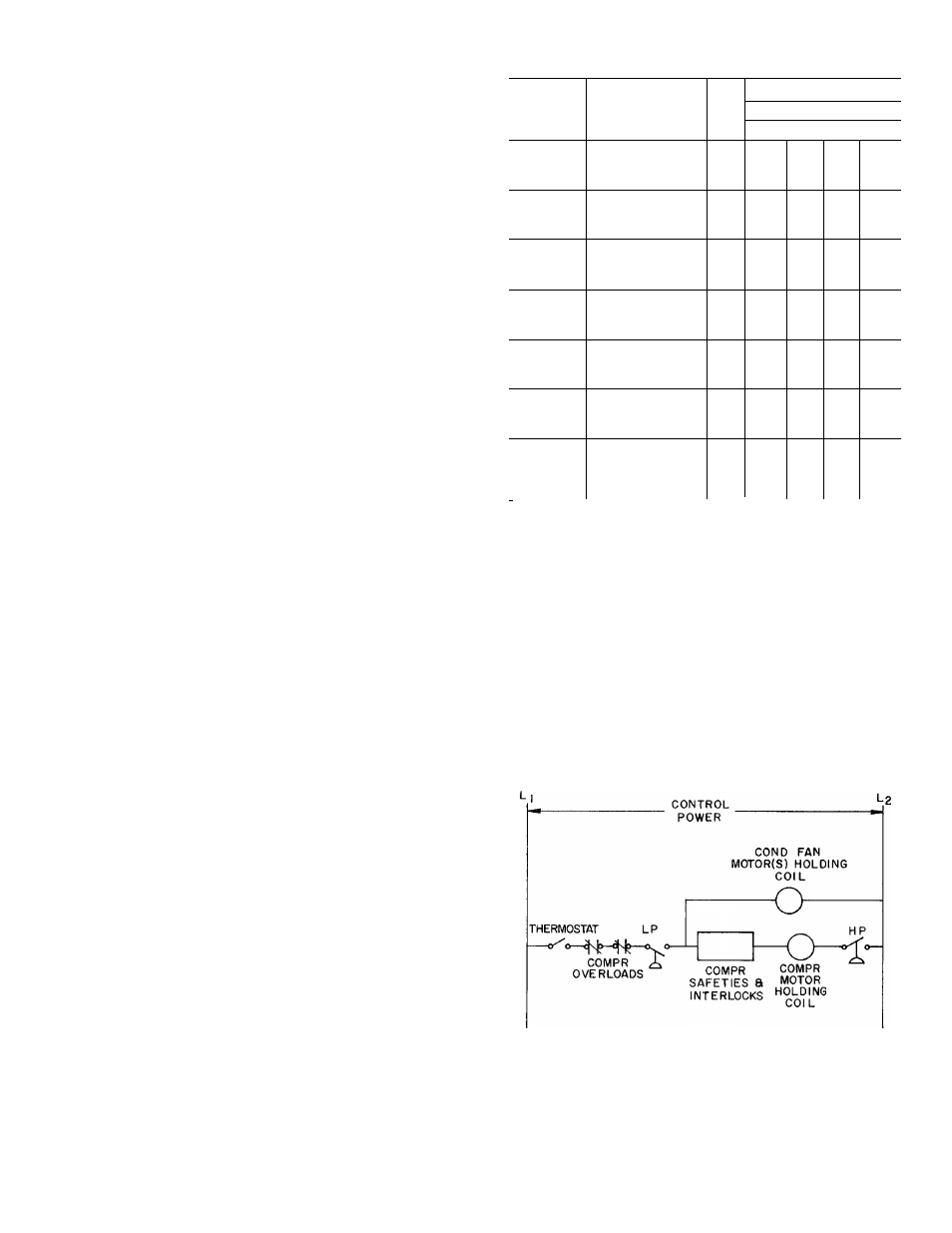
SCHEMATIC WIRING DIAGRAM
— CONDENSER CONTROL
(Single Refrigerant Circuit, Single Phase)
LP
— Low Pressure Switch
^
HP
— High Pressure Switch
NOTES:
1. For three-phase service, holding coils are wired in parallel.
2.
Multicircuit
units
may
be
similarly
controlled
by
wiring
fan
motor
holding
coil(s)
in
series
with
thermostat,
compressor
overloads,
and low pressurestat of each refrigerant circuit
3.
Two
or
more
condensers,
piped
in
parallel
on
a
single
refrig
erant circuit, must be of equal size and wired in parallel.