Condenser ratings, Condenser ratings typical arrangements – Carrier 09DC User Manual
Page 3
Attention! The text in this document has been recognized automatically. To view the original document, you can use the "Original mode".
CONDENSER RATINGS
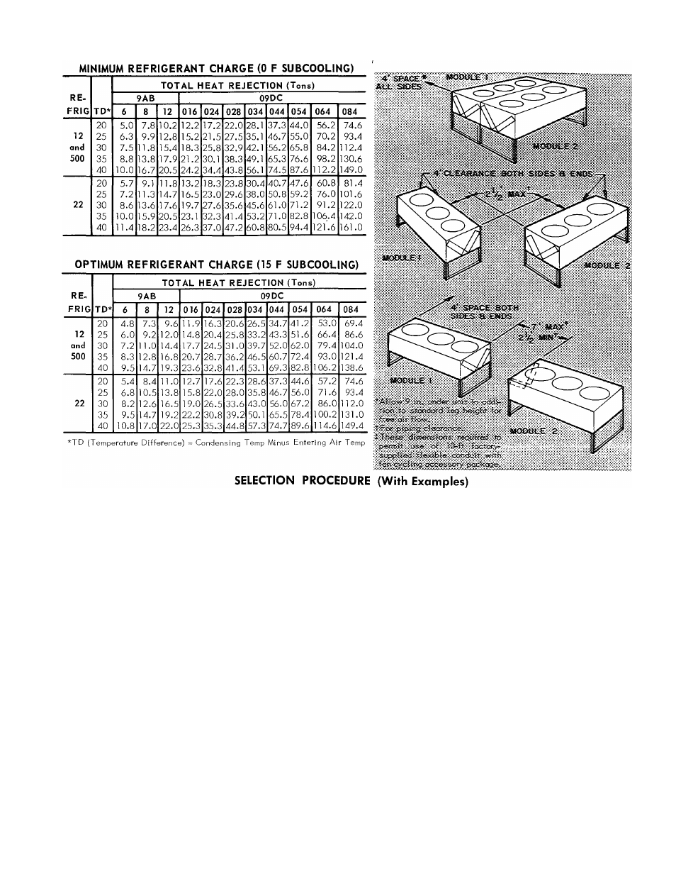
TYPICAL ARRANGEMENTS
(Two-Module Condensers)
la. Select minimum or optimum charge ratings.
Use
optimum
charge
when
compressor,
condenser,
and
evaporator
may
be
selected
as
a
package
and
the
com
ponents
may
be
balanced*
to
secure
maximum
benefits
of
15
F
subcooling
(for
example,
in
selecting
09DC
con
densers
with
Carrier
compressors
rated
at
15
F
sub
cooling).
Optimum
charge
activates
the
subcooling
circuit,
resulting
in
higher
system
capacity
at
slightly
higher
head
pressure
and
corresponding
condensing
temperature.
Liquid
refrigerant
leaves
the
system
sub
cooled
to
a
stable
condition
to
allow
greater
length
of
refrigerant run or lift.
Otherwise,
use
minimum
charge
which
gives
higher
heaf
rejection,
since
entire
surface
of
condenser
and
sub
cooling
circuit
is
used
for
condensing
only.
Minimum
charge
ratings,
however,
do
not
represent
greatest
po
tential
system
capacity.
They
are
comparable
to
com
petitive ratings without subcooling.
b.
List
the
refrigerant,
total
heat
rejection
(THR),
suction
and
discharge
temperatures
as
determined
from
com
pressor data.
2.
Determine
condensing
temperature
(saturated
discharge
temperature minus discharge line loss).
3.
Determine
temperature
difference
(condensing
tempera
ture minus entering air temp).
4.
Enter
Condenser
Ratings
table
(minimum
or
optimum
charge
as
determined
in
Step
1)
at
selected
refrigerant
and
established
temperature
difference.
Read
across
to
total
heat
rejection
equal
to
or
greater
than
required.
Interpolate if necessary. Read unit size.
Example
(Optimum Charge)
1. Given:
R-22, Optimum Charge
THR (including subcooling).......................................................... 29.4 Tons
Saturated Disch Temp................................................................................ 123.8 F
Saturated Suction Temp.................................................................................. 40 F
Entering Air Temp............................................................................................95 F
Disch Line Loss................................................................................................. 2 F
2.
CondTemp^ 123.8F-2F= 121.8F
3.
TD = 121.8F-95F- 26.8 F
4.
Interpolate
in
Condenser
Ratings
table
(optimum
charge)
and
obtain
capacity
of
09DC028 as
30,0 tons and 09DC024
as 23.6 tons. Select the 09DC028.
Example
(Minimum Charge)
1. Given:
R-12, Minimum Charge
THR . . ■.................................................................................... 15.0 Tons
Saturated Disch Temp...................................................................................122 F
Saturated Suction Temp..................................................................................40 F
Entering Air Temp........................................................................................... 95 F
Disch Line Loss ............................................................................................ 2 F
2.
Cond Temp = 122 F-2 F - 120 F
3.
TD= 120 F-95 F-25 F
4.
Enter
Condenser
Ratings
table
(minimum
charge)
and
select
09DC016
with
15,2
tons
THR.
(Note
that
with
optimum
charge
this
unit
has
THR
of
14.8
tons
which
does not meet specifications).
*See Carrier System Design Manual.