Electrical data and wiring – Carrier 50MQ User Manual
Page 4
Attention! The text in this document has been recognized automatically. To view the original document, you can use the "Original mode".
ELECTRICAL DATA AND WIRING
Field wiring must comply with local and
national fire, safety and electrical codes. Voltage to
unit must be within ±10% of voltage indicated on
nameplate. On 3-phase units, phases must be
balanced within 2%.
Operation of unit on improper line voltage or ;
with e.xcessive phase unbalance constitutes
abuse and is not covered by Carrier Warranty.
See Table 2 for recom m ended wire and fuse sizes
Step 7 — Install a Branch Circuit Fused Disconnect
of adequate size to handle unit starting current.
Locate disconnect within sight of and readily
accessible from the unit. (Use a separate fused
disconnect(s) for each electric circuit as required.)
Step 8 — Bring Line Power Leads Into Unit.
Extend leads from fused disconnect thru hole pro
vided (Fig. 1) into line wiring splice box (Fig, 5).
Step 9 — Connect Ground Lead to Ground Lug in
Splice Box
before connecting power wiring. See Fig.
6. Connect line power leads to yellow and black
pigtails on single-phase units or yellow, blue and
black pigtails on 3-phase units. Use wire nuts
'provided. Tape each connection. Wire nuts are
suitable for copper or aluminum wire since they
contain joint compound.
Step 10 — Set Indoor Fan Motor Speed
— (Refer
to page 2 for minimum allowable air quantity for
safe electric heater operation). Four-speed indoor
fan motor is factory wired for high speed opera
tion. Fan motor is equipped with spade-type speed
selector terminals marked 1, 2, 3 and 4. For lower
fan speed, remove black
unit
lead from motor
spade terminal 1 and connect to spade terminal 2,
3 or 4. On alternate fan motors remove black
m otor
lead from unit connection and replace with
blue, orange or red motor lead.
MOTOR LEAD
MOTOR TERMINAL
FAN SPEED
Black
H i g h
B lue
2
Medium
H i g h
Orange
Red
3
4
Med ium
Low
Low
Step 11 — Control Power Wiring (24 v)
is brought
through 7/8-in. hole provided in unit. Fig. 1.
Extend leads to unit control wiring terminal board.
Fig. 5. Connect leads to terminal board as directed
in Fig. 7.
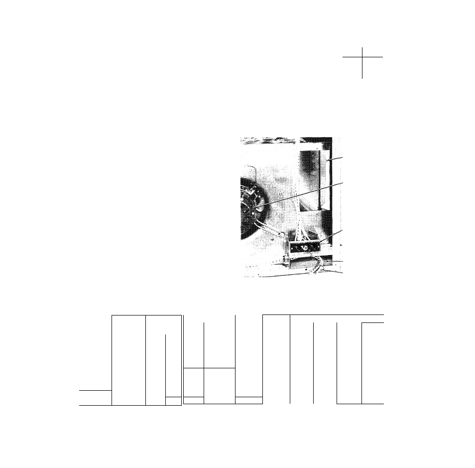
HEATER
INSTALLATION
AREA
INDOOR FAN MOTOR
CONTROL WIRING
TERMINAL BOARD
WIRING KNOCKOUTS
■AND HOLES
(HIDDEN) SEE FIG t
LINE WIRING
SPLICE BOX
LINE VOLTAGE PIGTAILS
Fig. 5 — Unit Wiring Terminal Location
Table 2 — Unit Electrical Data
OPER
MODEL
V/PH
VOLTAGE*
Max
Min
50MQÒ22
■
—
50MQ027
S0MQ032
50MQ037
200/1
220
180
50MQ022
50MQ027
50MQ032
50MQ037
230/1
254
207
50MQ032
200/230/3
254
180
50MQ037
200/230/3
254
180
COMPRESSOR
IFM
OFM
BRANCH CIRCUIT
Power
Max
Gnd
Max
LRA
FLA
FLA
FLA
Wire
Ft
Wire
Fuse
Size
W ire
Sizet
Amps
(AWG)
(AWG)
75
14.1
2 2
2.2
10
40
10
35
80
16.2
2.2
2.2
10
35
10
40
99
20.8
3.6
2 2
8
43
10
50
112
26.5
3.9
2.2
8
35
10
60
68
12 8
2.0
1 9
12
32
12
30
72
14 0
2.0
1.9
10
47
10
35
88
18 0
3 1
1 9
10
36
10
45
100
23.0
3.4
1.9
8
45
10
50
75
13.0/11.5
3.6/3.1
2.2/1.9
10/12
50/42
10/12
35/30
80
15.0/12 8
3.9/3.4
2.2/1.9
10/10
45/60
10/10
35/30
FLA
— Full Load Amps
LRA
— Locked Rotor Amps
IFM
— Indoor Fan Motor
OFM
— Outdoor Fan Motor
"Permissible limits of the voltage range at which the units will
operate satisfactorily.
tRequIred when using nonmetallic conduit.
N O T E S :
1. Fan motors are 200w or 230-v, single-phase.
2. All units equipped with 24-v transformer for external control circuit.
3. Copper wire sizes based on 60 C. Aluminum field wiring may be used
when spiice connected to copper pigtails from unit with factory-
supplied wire nuts. Use latest National Electrical Code for aluminum
wire sizing.