Cooling cycle condensate disposal, Electric heater installation, Condensate – Carrier 50MQ User Manual
Page 3
Attention! The text in this document has been recognized automatically. To view the original document, you can use the "Original mode".
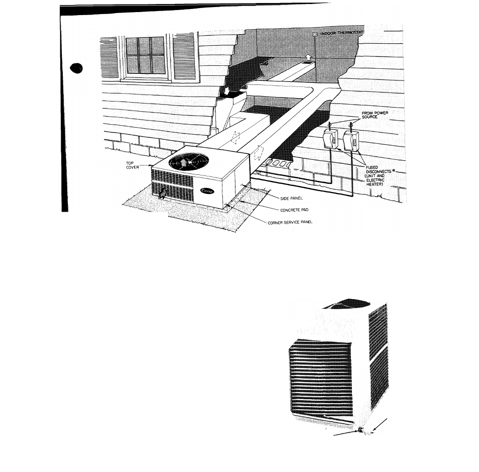
— POWER WIRING
-------CONTROL WIRING
OUTDOOR
air
flow
INDOOR AIR FLOW
pUMP
«Separate fused disconnect required for electric heater.
Fig. 3 — Typical Installation
COOLING CYCLE CONDENSATE DISPOSAL
Condensate may be drained directly onto gravel
apron or connected by drain line(s) to a dry well
Condensate disposal methods must comply with
local codes and practices.
Step 6 - Connect a Drain Line
to rubber conden
sate drain fitting on side of unit (see Fig. 1). Use
clamp provided. Install factory-supplied conden
sate trap (taped to indoor fan housing for ship
ment) at end of drain line. If a drain line is not
used, connect condensate trap to unit drain fitting
as shown in Fig 4.
ELECTRIC HEATER INSTALLATION
For complete heater installation data, including
accessory outdoor thermostat and emergency heat
switch, refer to accessory electric heater Installa
tion, Start-Up and Service booklet. Complete
control wiring connections are shown in this
booklet.
CONDENSATE
DRAIN TRAP
CONDENSATE DRAIN FITTING
WITFI CLAMP
Fig. 4 -
Condensate
Drain Connection