A warning, Refrigerant charging (refer to fig. 6 and table 5), A caution – Carrier 38EN User Manual
Page 4: Step 5 — start-up, 38en air-cooled condensing units
Attention! The text in this document has been recognized automatically. To view the original document, you can use the "Original mode".
HEATING A COOLING
38EN
Air-Cooled Condensing Units
INSTALL BRANCH CIRCUIT DISCONNECT PER
NEC of adequate size to handle unit starting current.
Locate disconnect within sight from and readily acces
sible from unit, per Section 440-14 of National Electrical
Code (NEC).
ROUTE LINE POWER LEADS — Extend leads from
disconnect through power wiring hole provided (see
Fig. 1) and into unit splice area. Remove control box
cover to gain access to unit wiring.
CONNECT GROUND LEAD AND POWER WIRING
— Connect ground lead to ground connection in control
box for safety. Then connect power wiring. See Fig. 4.
Splice line power leads to yellow and black pigtails. Use
wire nuts and tape at each connection. Connect unit
wiring to copper power wiring only.
CONNECT CONTROL POWER WIRING — Route
24-v control wires through control wiring hole and
connect to pigtails supplied with unit (Fig. 1). Splice
control leads to brown and blue pigtails on all units.
See Fig. 5.
Use furnace or fan coil transformer as 24-v (40-va
minimum) supply for system as shown in Fig. 5, or use
accessory transformer (refer to Service Data).
NOTE: Some 38EN units are equipped with a fan time
delay. This permits indoor fan to continue to operate for
90 seconds, which provides additional cooling after
compressor has eyeled off. Refer to separate installation
instructions packaged with fan time delay (shipped
with unit).
A
WARNING
To
avoid
personal
injury,
be
sure
indoor
blower has stopped before attempting service
or maintenance.
Refrigerant Charging (Refer to Fig. 6
and Table 5)
A
CAUTION
To prevent personal injury, wear safety glasses
and gloves when handling refrigerant. Do not
overcharge system. This can cause compressor
flooding.
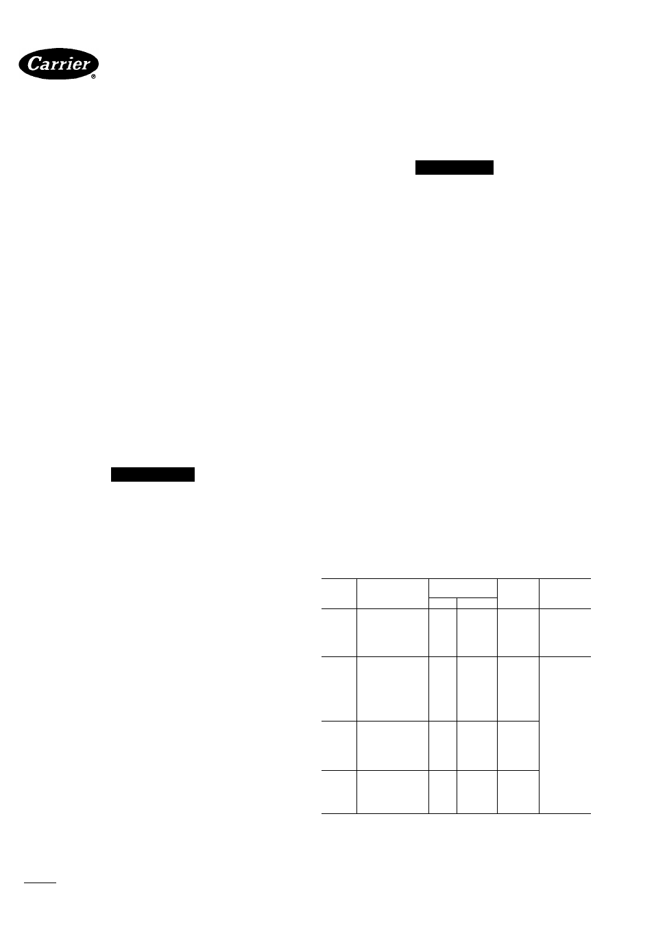
I-PHASE
CONN. TO
DISCONNECT
PER NEC
-GROUND LEAD
-C®1
grounding
lug
-
— BLK----------------
YEL-
1- PHASE
COND UNIT
3-PHASE
CONN. TO
DISCONNECT
PER NEC
r__________________
BLK -
BLU-
• YEL -
--GROUND LEAD --J-SGROUNDING LUG
3-PHASE COND UNIT
—
fr-i
— SPLICE CONNECTIONS
-------------- FIELD WIRING
-------------- FACTORY WIRING
Fig. 4 — Line Power Connections
Table 4 — Service Data
Step 5 — Start-Up
1. Energize crankease heater a minimum of 24 hours
before starting unit. To energize heater only, set
thermostat at OFF position and close electrical dis
connect to outdoor unit.
2. Backseat (open) liquid and suction line serviee valves.
3. Set thermostat selector switch at OFF.
4. Set room thermostat at desired temperature. Be sure
set point is below indoor ambient temperature.
5. Close electrieal diseonnects to energize system.
6. Set room thermostat at COOL and fan switch at FAN
or AUTO, as desired. Operate unit for 15 minutes.
Check system refrigerant charge. See Refrigerant
Charging, below.
Motors and controls are designed to operate satis-
faetorily in the voltage range shown in Table 3. If
necessary to use manifold gages for servicing, refer to
Carrier Standard Service Techniques Manual, Chapter 1,
Refrigerants, page 1 - 5, Fig. 8, for bypass method of
returning charge to system. Removal of liquid line
eharging hose without following these precautions could
result in some loss of charge.
MODEL
38EN
COMPRESSOR
OIL
CHARGE (oz)
R-22
CHG* (lb)
OUTDOOR
FAN RPM
Initial
Recharge
015300
REK3-0125-PFV
24
20
3 60
015310
AK8515E
17
15
3 20
018300
H21B193ABCA
40
37
3 60
1650
018310
RES3-0175
24
20
3 70
024300,
H21B243ABCA
40
37
3 80
310
030300
H21A313ABCA
40
37
5 60
030320
MD3215GG
46
44
6 70
036300,
H21A373ABCA
50
47
5 80
320
042300
H21A463ABCA
50
47
7 20
048300
PC5316BD
76
62
7 60
060300,
PC6716AG
76
62
9 60
310
PC6716AG
76
62
12.50
030500
H21A313DBD
40
37
5 60
036500
H21A373DBD
50
47
5 80
1100
042500
H21A463DBD
50
47
7 20
048500
PY5316AD
76
62
7 60
060500,
PY6716AF
76
62
9 60
510
PY6716AF
76
62
12.50
036600
H21A373DBE
50
47
5 80
042600
H21A463DBE
50
47
7 20
048600
PH5316AD
76
62
7 60
060600,
PH6716AF
76
62
9 60
610
PH6716AF
76
62
12 50
'Factory refrigerant charge is adequate when indoor unit and outdoor unit
are the same size and are connected with 25 ft or iess of fieid-suppiied
tubing of recommended size or Carrier accessory tubing
Manufacturer reserves the right to discontinue, or change at any time, specifications or designs without notice and without incurring obligations.
Book|1 |4
PC 101 Catalog No. 563-825 PrintedinUSA Form38EN-3SI Pg4 485
12-84 Replaces: 38EN-2SI