Carrier 38EN User Manual
Installation and start-up instructions, 38en air-cooled condensing units
Attention! The text in this document has been recognized automatically. To view the original document, you can use the "Original mode".
HEATING A COOLING
38EN
Air-Cooled Condensing Units
Installation and Start-Up Instructions
SAFETY CONSIDERATIONS
Installing and servicing air conditioning equipment
can be hazardous due to system pressure and electrical
components. Only trained and qualified service personnel
should install or service air conditioning equipment.
Untrained personnel can perform basic maintenance,
such as cleaning and replacing filters. All other opera
tions should be performed by trained service personnel.
When working on air conditioning equipment, observe
precautions in literature and on tags and labels attached
to unit.
Follow all safety codes. Wear safety glasses and work
gloves. Use quenching cloth for brazing operations.
Have fire extinguisher available. Read these instruc
tions thoroughly. Consult local building codes and
National Electrical Code (NEC) for special installation
requirements.
A WARNING
Before installing or servicing system, always turn
off main power to system. There may be more
than one disconnect switch. Turn off accessory
heater power if applicable. Electrical shock can
cause personal injury.
#
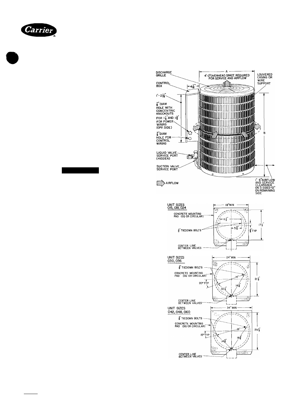
Step 1 — Check Equipment and Jobsite —
Install on a solid, level mounting pad. It is not recom
mended that unit be attached to pad using tiedown bolts.
Fasten unit to pad using holes provided in unit mounting
feet. See Fig. 1.
When installing, allow sufficient space for airflow
clearance, wiring, refrigerant piping and service. Main
tain a minimum of 4 ft clearance from obstructions above
and 18 in. on 3 sides of unit (12 in. on fourth side). Main
tain a distance of 24 in. between condensing units. Posi
tion so water or ice from roof or eaves cannot fall directly
on unit.
Step 2 — Replace Indoor AccuRater™ Piston,
if required.
REPLACE
ACCURATER
REFRIGERANT
CON
TROL PISTON in the indoor coil, if required, before
connecting refrigerant lines. Refer to Table 2 for proper
piston size.
Step 3 — Make Piping Connections — Outdoor
units may be connected to indoor sections using Carrier
accessory tubing package (refer to Service Data) or
field-supplied tubing of refrigerant grade, correct size
(see Table 1) and condition. For tubing requirements
beyond 50 ft, obtain information from your local
distributor.
Outdoor Units Connected to Carrier-Approved
Indoor Units — Outdoor units contain correct system
refrigerant charge for operation with indoor unit of the
same size when connected by 25 ft of field-supplied or
Carrier accessory tubing. Check refrigerant charge for
maximum efficiency (see Refrigerant Charging, page 4
and Service Data).
Certified dimension drawings avaiiabie upon request
Fig. 1 — Dimensions, Connections and
Mounting Pad (Refer to Table 1)
Manufacturer reserves the right to discontinue, or change at any time, specifications or designs without notice and without Incurring obligations.
Book И |4
PC101 Catalog No 563-825 PrintedinUSA Form38EN-3SI Pg 1
485
12-84 Replaces: 38EN-2SI
Pnr rAnlar^AmArtt Млтв iiea
Tab |3a|2a