Table 5 - electrical data – Carrier 50K User Manual
Page 4
Attention! The text in this document has been recognized automatically. To view the original document, you can use the "Original mode".
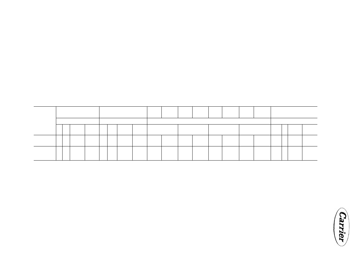
TABLE 5 - ELECTRICAL DATA
Current
Characteristics
Locked Rotor Current
Amps.
Full Load Current
Amps.
Wire
Size
Awg. No.
Max. Wire
Length
Ft.
Wire
Size
Awg. No
Max. Wire
Length
Ft.
Wire
Size
Awg. No.
Max. Wire
Length
Ft.
Wire
Size
Awg. No.
Max. Wire
Length
Ft.
Dual Element Fuse Size
Amps.
50K
50K
50 K
50K
8
12
16
(1 Com.p.)
16
(2 Comp.)
8
12
16
(1 Comp.)
16
(2 Comp.)
8
12
16
(i Comp.)
16
(2 Comp.)
8
12
16
(1 Comp.)
16
(2 Comp.)
8
65
6
100
4
98
8
80
208/220-3-60
120
180
250
120
24.9
35.7
55. 6
24.9
6
100
4
160
2
145
6
125
35
60
SO
35
4
155
2
235
1
185
4
195
12
135
10
170
8
160
12
135
440-3-60
60
90
125
60
11.9
17.5
27.2
11.9
10
210
8
260
6
250
10
210
17-1/2
25
40
17-1/2
8
325
6
400
4
390
8
325
KOTES; 1. Wire sizes, lengths, fuse sizes, and dual element fuse sizes snown are for the branch circuit between the disconnect switch and the unit.
2. The branch circuit wire sizes and the corresponding maximum wire lengths tabulated will result in a
1
%
voltage drop at the nameplate full load amperage. The ware size listed and the maximum fuse sizes are
m accordance with the National Electric Code.
3. Dual element fuses can be sized much closer to the actual running current than one-time link type fuses because of the built-in lag. Thus, dual element fuses give additional motor protection against both
single phasing and locked rotor failure, should starter contacts fuse. Use dual element fuses for compressor protection on all installations. With properly selected fused disconnect switches, fuse reducers
may be required.
z
(/»
>
>
o
z