Carrier, Installation – Carrier 50K User Manual
Page 2
Attention! The text in this document has been recognized automatically. To view the original document, you can use the "Original mode".
50K
INSTALLATION
Carrier
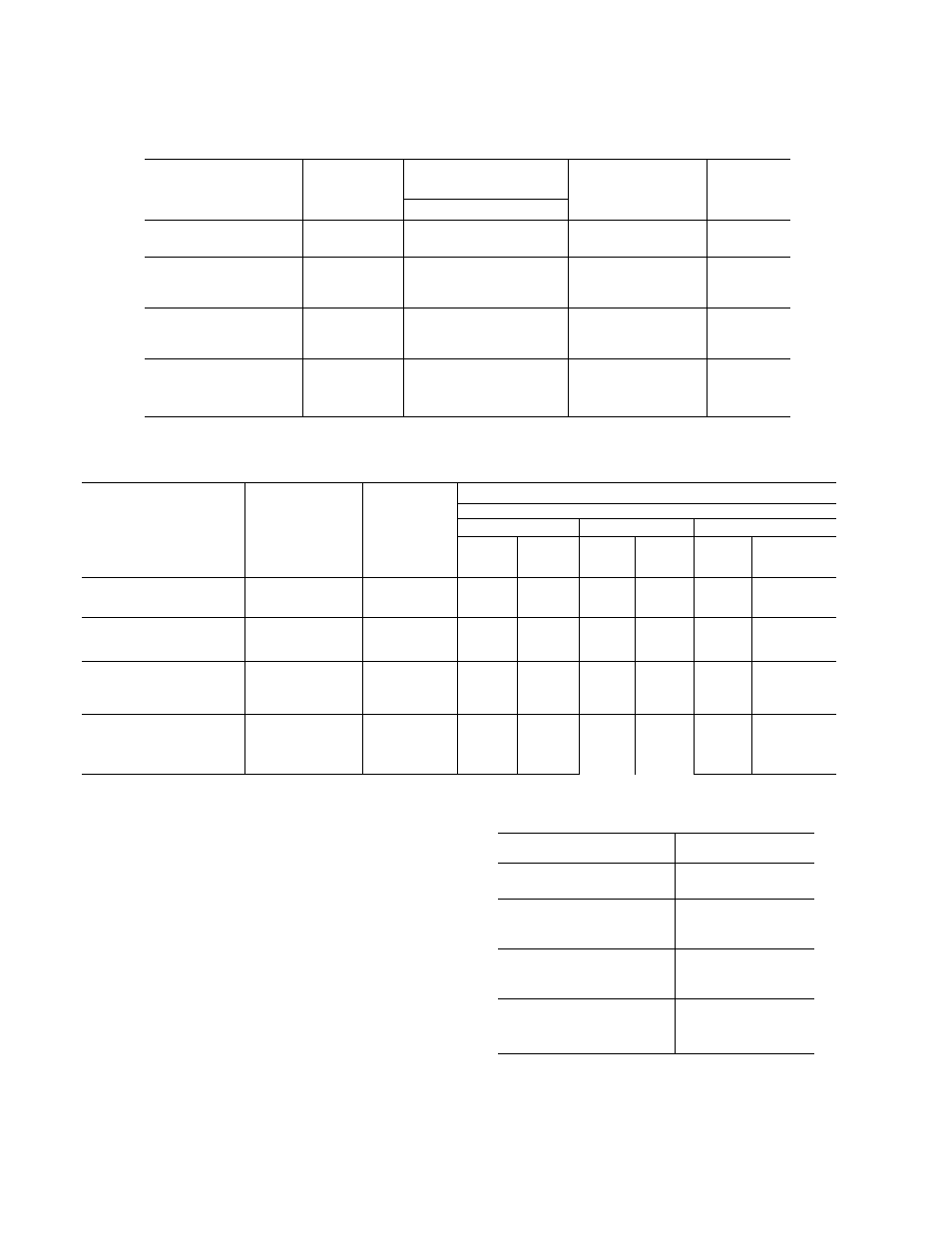
TABLE 1
Unit
Circuit No
Compressor
Evaporator Coil
Liquid Line
Connection
R-22
Pounds
Model
Location
50K8
(1 Circuit)
6D48
-
-
10
50K12
Single Compressor
(1 Circuit)
6D68
-
-
10
50K16
Single Compressor
(1 Circuit)
6D75
_
-
15
50K16
No. 1
6D48
Left Side
Right End
10
2 Compressor
No. 2
6D48
Right Side
Left End
10
TABLE 2
Recommended Line Sizes
Linear Feet Piping
20
40
60
Discharge Line
Liquid Line
Liquid
Hot
Liquid
Hot
Liquid
Hot
Unit
Connection
Connection
Line
Gas
Line
Gas
Line
Gas
50K8
7/8
1/2
1/2
7/8
1/2
7/8
1/2
7/8
50K12
Single Compressor
7/8
5/8
5/8
7/8
5/8
1-1/8
3/4
1-1/8
50K16 (Ea. Circuit)
2 Compressor
7/8
1/2
1/2
7/8
1/2
7/8
1/2
7/8
50K16
Single Compressor
1-1/8
5/8
5/8
1-1/8
3/4
1-1/8
3/4
1-3/8
REFRIGERANT CHARGE
The unit will be shipped with a 2 lb. holding charge
of Refrigerant 22. In the standard installation,
Refrigerant 22 will be used. However, on special
applications. Refrigerant 500 may be used. Con
sult your Application Engineering Data for informa
tion concerning the use of Refrigerant 500. When
Refrigerant 500 is used, change the expansion valve
to the one shown in Table 3.
REFRIGERANT CHARGE QUANTITY
During operation on Refrigerant 22 the base unit
alone requires the number of pounds shown in Table 1.
To this, add the needs for the refrigerant lines, con
densers, and receivers (if used). Stamp the number
of pounds used in the blank space provided on the
nameplate.
TABLE 3 - VALVES FOR R-500 SERVICE
Unit
Sporlaii Valve
50K8
PDE6G
50K12
Single Compressor
PDE9G
50K16
Single Compressor
PDE13G
50K16
PDE6G
2 Compressor
(2) required
DUAL PRESSURESTATS
Adjust the pressurestats according to pressure shown
in Table 4.